Model
333A/334A
Section
V
3V RANGE
FREQ. METER INDICATION FREQ.
MIN.
MAX.
I
2.94
V
2.94
V
2.94
V
2.94 V
2.94
V
2.85
V
2.85
V
0.0003V RANGE
METER INDICATION
MIN.
MAX.
3.06
V
3.06
V
3.06
V
3.06
V
3.06V
3.15V
3.15V
20
Hz
30
Hz
1
kHz
10
ma
100
kFiz
300
k?Iz
500
kHz
285 pV 315
pV
294 pV 306pV
294 pV
306
pV
294 pV
306
pV
294 pV
306
pV
294 pV
306
pV
285 pV 315
pV
h.
t
j.
k
1.
Set test oscillator to
400Hz, and adjust
amplitude
until
333A/334A meter indication
is
3
V.
Set
reference on meter
of
test
oscil-
lator and use amplitude control to maintain
set
reference whenever frequency
of
oscil-
lator
is
varied.
Set
test
oscillator to each frequency lMed
in
Table 5-2. At each
respective
frequency,
333A/334A meter
reading
should
be
within
tolerances listed
in
table.
Set 333A/334A METER RANGE switch to
0.0003
VOLTS.
Set
test
oscillator to 400
Hz,
and
adjust
amp-
litude
until
333A/334A meter indication
is
300
pV. Set
a
reference on meter
of
test
oscillator and use amplitude control to main-
tain
set
reference whenever frequency
of
oscillator
is
varied.
Set
test
oscillator to each frequency listed
in
Table 5-4.
At
each respective frequency,
333A/334A meter reading should
be
within
tolerances listed
in
table.
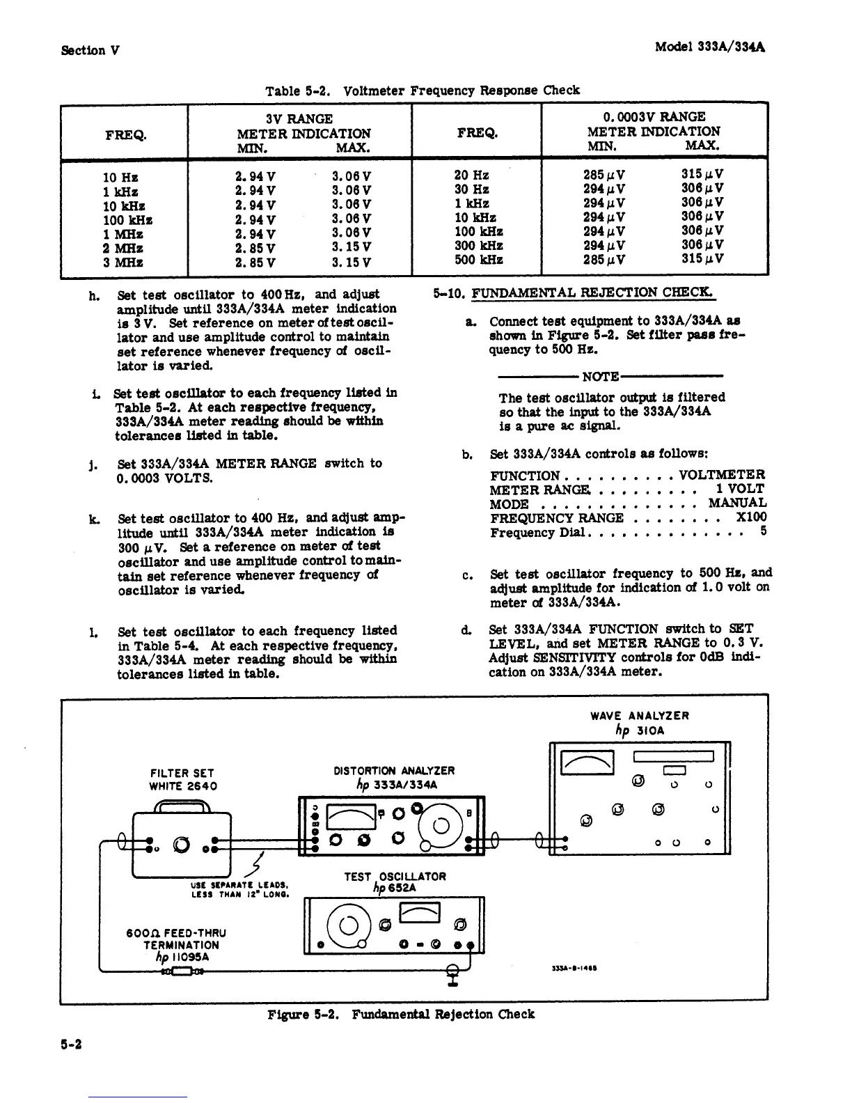
5-10.
FUNDAMENTAL REJECTION CHECK
a.
Connect
test
equipment to 333A/334A
88
shown
in
Fee
5-2. Set
filter
pass
fre-
quency to 500
Hz.
NOTE
The
test
oscillator
output
ie
filtered
so
that
the input to the 333A1334A
is
a
pure
ac
signal.
Set 333A/334A controls
as
follows:
FUNCTION
..........
VOLTMETER
METER RANGE
.........
1
VOLT
MODE
..............
MANUAL
FREQUENCY RANGE
........
XI00
Frequency Dial.
.............
5
b.
c.
Set
test
oscillator frequency to
500
Hc,
and
adjust
amplitude for indication
of
1.0
volt on
meter
of
333A/334A.
Set 333A/334A FUNCTION switchto SeT
LEVEL,
and
set
METER RANGE to
0.3
V.
Adjust SENSITIVITY controls for
OdB
indi-
cation on 333A/334A meter.
6
WAVE ANALYZER
hp
310A
FILTER
SET
WHITE
2640
3S3&-@-14e6
Figure
5-2.
Fundamental Rejection Check
5-2
 Loading...


