Section
V
REGULATION
'%.
5 and 126.5 VAC)
ADJUSTMENT line voltage between
MEASUREMENT VOLTAGE
POINT
LIMITS
I
Any violet wire
-25 V
i
0.5
V
AlR13 -25
V
f
0.25
V
Any red
wire
+25
Vf
1.0
V
None
*
+25
V
f
1.0
V
A2
TP1
-11.3
v
A2R3
-11.3
v
&.
1
v
Aa
TP2
+8.2
V
i
0.5
V
MR20
,+8.2
V
f
0.5
V
A3 TP1 +2.65
V
f
0.2 V
A3
R4
+2.65
V
f
0.2
V
A3 TP2
-19.5
v
f
0.5
v
A3R16 -19.5
v
f
0.5
v
*Referencedto-25 volt supply; -25 volt supply must
be
adjusted
first.
STO-O-OOOB
-
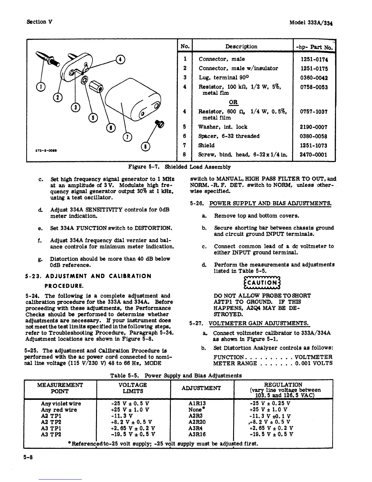
No.
1
2
3
4
-
4
5
6
7
8
-
Description
Connector, male
Connector, male w/indator
Lug, terminal 900
Resistor, 100
kS1,
1/1
W,
58,
metal
flm
OR
-
Resistor,
600
a,
1/4
W,
0.5%
Washer,
int.
lock
Spacer,
6-32 threaded
Shield
Screw,
bind. head, 6-32
x
1/4
in.
metal film
-hp-
Part
NO.
1251 -0174
1251-0175
0
3
60-0042
0758-0053
-
0757-1037
2
190
-0007
0
380
-0058
1251-1073
2470-0001
Figure
5-7. Shielded Load Assembly
c.
Set
high frequency
signal
generator to
1
MHz
at
an amplitude
of
3V. Modulate high
fre-
quency
signal
generator
output
30%
at
1
kHz,
using
a
test
oscillator.
Adjust 334A SENSITIVITY controls
for
OdB
meter indication.
d,
e.
f.
Set
334A FUNCTION switch to DISTORTION.
Adjust 334A frequency
dial
vernier and bal-
ance controls for minimum meter indication.
g.
Distortion should
be
more than 40 dB below
OdB reference.
5-23.
ADJUSTMENT AND CALIBRATION
PR
0
CED
U
RE.
5-24. The following
is
a
complete adjustment and
calibration
procedure
for
the 333A and 334A. Before
proceeding with these adjustments, the Performance
Checks should
be
performed to determine whether
adjustments
are
necessary.
If
your
instrument does
not meet the
test
limits specified
in
the following
steps,
refer
to Troubleshooting
Procedure,
Paragraph 5-34.
Adjustment locations
are
shown
in
Figure
5-8.
5-25. The adjustment and Calibration Procedure
ie
performed with the
ac
power cord connected to nomi-
nal
line voltage (115 V/230
V)
48
to
66
He, MODE
switch to MANUAL, HIGH PASS FILTER TO OUT,
and
NORM.
-R
F.
DET. switch to NORM,
unless
other-
wise specified.
5-26. POWER SUPPLY AND BIAS ADJUSTMENTS.
a.
b.
Remove top and bottom covers.
Secure shorting bar between chassis ground
and circuit ground INPUT terminals.
c. Connect common lead of
a
dc voltmeter to
either INPUT ground terminal.
Perform the measurements and adjustments
listed in Table 5-5.
d.
DO
NOT ALLOW PROBE
TO
SHORT
A2TP1 TO GROUND.
IF
THIS
HAPPENS,
A2Q4
MAY BE DE-
STROYED.
5-27. VOLTMETER GAIN ADJUSTMENTS.
a.
Connect voltmeter calibrator to 333A/334A
as
shown
in
Figure
5-1.
b.
Set
Distortion Analyzer controls
as
follows:
FUNCTION.
.
. .
. .
.
.
.
. VOLTMETER
METER RANGE
.
.
. . . .
. 0.001 VOLTS
 Loading...


