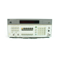
Model 8901B Operation
3-12.
BASIC FUNCTIONAL CHECKS OF THE MODULATION ANALYZER
Description
Using a signal generator, an oscilloscope, and a sensor module, the overall operation of the Modulation
Analyzer
is
verified.
Equipment
Oscilloscope
......................................................................
HP 1740A
Sensor Module
..................................................................
HP 11722A
Signal Generator..
.............................................
HP
8640B Option 001 and 002
The HP 8656B, HP 8662A, HP 8663A, HP 8654A
or
HP 8654B can also be used
if
an
HP 8640B
Option 001 and 002
is
not available. However, with these other signal generators you
will
need
to
modify
some tests.
Procedure
Preliminary Check
1.
Connect the multi-conductor cable of the sensor module
to
the SENSOR input connector.
Connect the RF coaxial cable of the sensor module
to
the INPUT 50R connector (see Figure
3-6). Select INSTR PRESET (Blue Key, AUTOMATIC OPERATION). Observe the front-panel
LED annunciators, display segments and decimal points, and key lights.
All
LEDs should light
for approximately 10 seconds
at
turn on and then all should momentarily turn
off.
2.
After
the turn-on sequence, the instrument should display
"--".
The MHz annunciator, the
FM annunciator under MODULATION OUTPUT, the AUTO TUNING annunciator (under the
TRACK MODE key), and the FREQ key should be lighted.
RF
Power Calibration Check
Connect the sensor module input to the RF POWER CALIBRATION OUTPUT connector. (See
Figure 3-6.)
Press the RF POWER key.
If
the instrument does not display Error 15, proceed with step 6.
If the instrument displays Error 15 (indicating the RF power calibration factors have not been
entered), proceed with step 5.
If
the instrument displays Error 15, enter the RF power calibration factors that are given on the
cover of the sensor module. (Note that a software driven alternative
is
available. See
RF
Power
for a program list in BASIC for the HP Series 200 computers.):
a. Enter the reference calibration factor by keying in 37.3 and pressing the SPCL key. Then,
key in the value of the reference calibration factor and press the Blue key then the
%
CAL
FACTOR key (the MHz key).
b. Enter each frequency/calibration factor pair by
first
keying in 37.3 and pressing the SPCL
key. Next, key in the frequency (in MHz) and press the MHz key. Then, key in the value of
the calibration factor and press the Blue key then the
9%
CAL FACTOR key.
NOTE
Error
15 will continue to be displayed until the Modulation Analyzer
is
able to interpolate between a frequencylcalibration factor pair from those
pairs entered.
(For
more information, refer to
RF Power Calibration
and
RF Power Calibration Factors
in the
Detailed Operating Instructions
in
this section.)
reu.1
OJUL87
3-47

 Loading...