Model
8901B
Adjustments
Adjustment
21
AUDIO TRUE
RMS
DETECTOR AND NOTCH FILTER GAIN
Service
Sheet
16
Description
The offset of the audio true
rms
detector
is
first adjusted
to
read zero with no audio input, then a
signal
of
known
level
is
applied
to
the detector and the sensitivity of the detector
is
adjusted
to
read
the correct level. The gain of the audio notch filter
is
adjusted for a reading of 100% with an input
signal
that
is
twice the frequency of the notch filter.
Equipment
Audio Oscillator
..................................................................
HP 8903B
Digital Voltmeter
.................................................................
HP
3455A
OUTPUT
AUDIO OSCILLATOR
INPUT
DIGITAL VOLTMETER
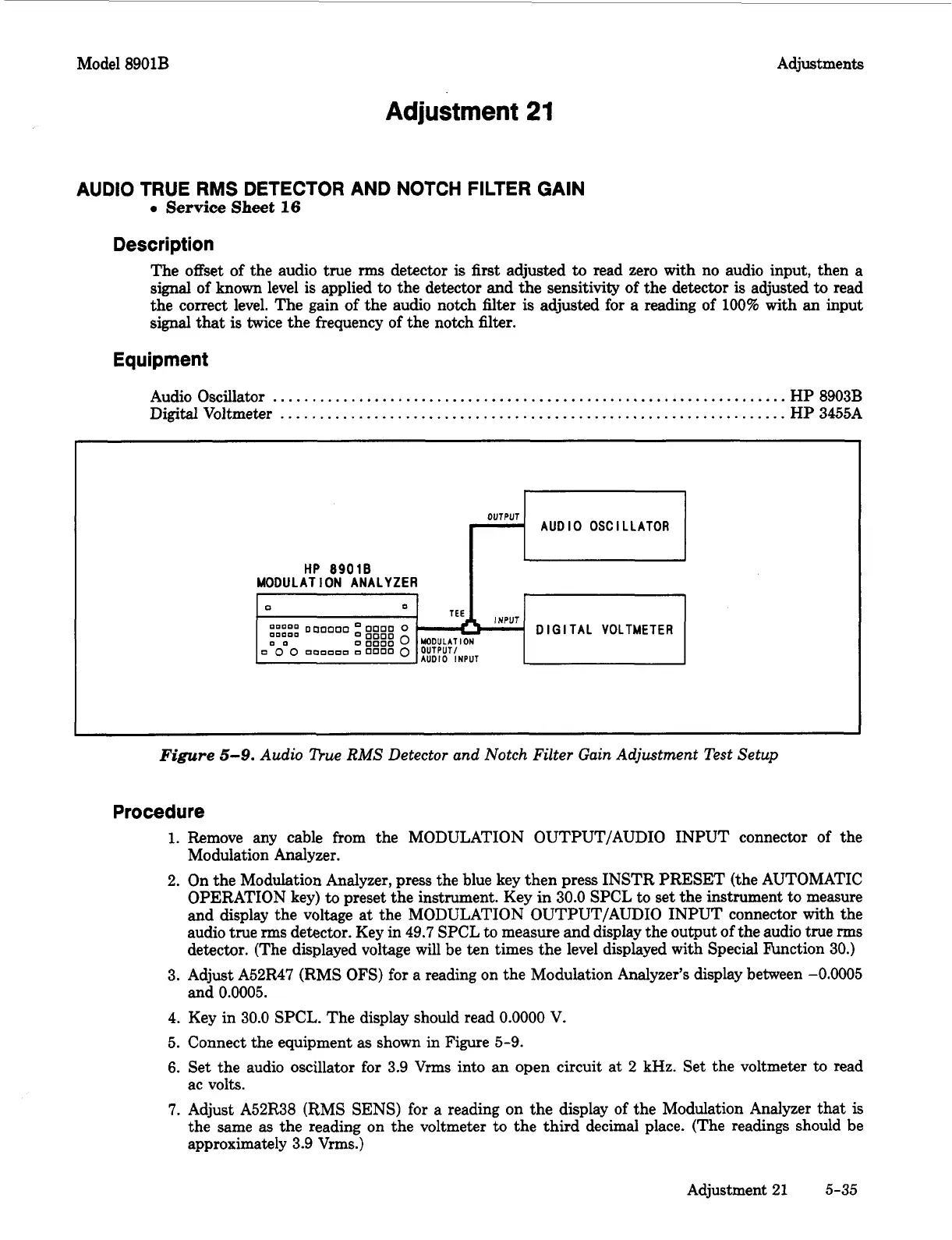
Figure
5-9.
Audio The
RMS
Detector and Notch Filter Gain Adjustment Test Setup
Procedure
1.
Remove any cable from the MODULATION OUTPUT/AUDIO INPUT connector of the
Modulation Analyzer.
2. On the Modulation Analyzer, press the blue key then press INSTR PRESET (the AUTOMATIC
OPERATION key)
to
preset the instrument. Key in 30.0 SPCL to set the instrument to measure
and display the voltage at the MODULATION OUTPUT/AUDIO INPUT connector with the
audio true
rms
detector. Key in 49.7 SPCL to measure and display the output of the audio true
rms
detector. (The displayed voltage will be ten times the level displayed with Special Function 30.)
3. Adjust A52R47 (RMS
OFS)
for a reading on the Modulation Analyzer’s display between
-0.0005
and
0.0005.
4. Key in 30.0 SPCL. The display should read
0.0000
V.
5.
Connect the equipment as shown in Figure 5-9.
6.
Set the audio oscillator for 3.9
Vrms
into an open circuit at
2
kHz. Set the voltmeter to read
ac volts.
7.
Adjust A52R38 (RMS
SENS)
for
a reading
on
the display of the Modulation Analyzer
that
is
the same as the reading on the voltmeter to the third decimal place. (The readings should be
approximately 3.9
Vrms.)
Adjustment 21
5-35