Adjustments Model 8901B
0
0
-
0
FM
OUTPUT
0
:::::
000000
:
;;;g
0
0
0
0
0 0
0
INPUT
00
0
0000
0
0 0
000000
0
0000
0
0
Adjustment
11
OUTPUT
AUDIO
SYNTHESIZER
FM
FLATNESS
0
Service
Sheet
11
Description
The AMFM
test
source
is
frequency modulated
at
a
1
kHz rate with 400 kHz peak deviation. The
demodulated FM
is
used as a reference. The modulation rate
is
increased
to
150 kHz
and
the FM
flatness
is
adjusted to bring the display back
to
the reference. The AMFM
test
source
is
required
to
assure
that the FM source
has
adequate bandwidth.
Equipment
AM/FM
Test Source
.............................................................
HP
11715A
Audio Synthesizer.
................................................................
HP
3336C
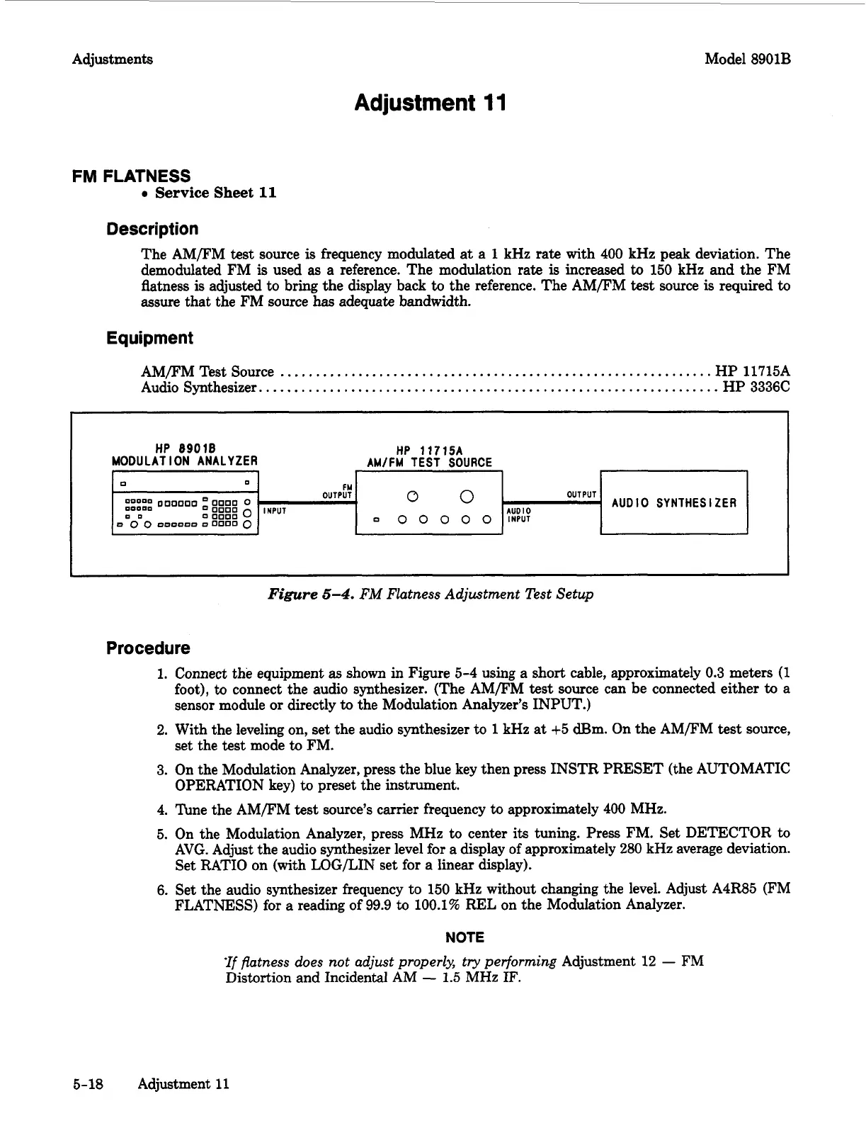
Figure
5-4.
FM
Flatness Adjustment Test Setup
Procedure
1.
Connect the equipment
as
shown
in
Figure 5-4
using
a short cable, approximately 0.3 meters
(1
foot),
to
connect the audio synthesizer. (The AMFM
test
source can be connected either
to
a
sensor module or directly to the Modulation Analyzer’s INPUT.)
2. With the leveling on, set the audio synthesizer
to
1
kHz at +5 dBm. On the AM/FM
test
source,
set the test mode
to
FM.
3. On the Modulation Analyzer, press the blue key then press INSTR PRESET (the AUTOMATIC
OPERATION key) to preset the instrument.
4. Tune the AMFM
test
source’s carrier frequency
to
approximately 400 MHz.
5. On the Modulation Analyzer, press MHz
to
center
its
tuning. Press FM. Set DETECTOR
to
AVG. Adjust the audio synthesizer level for a display of approximately
280
kHz average deviation.
Set RATIO on (with LOG/LIN set for a linear display).
6.
Set the audio synthesizer frequency to 150 kHz without changing the level. Adjust A4R85 (FM
FLATNESS) for a reading of
99.9
to
100.1%
REL on the Modulation Analyzer.
NOTE
‘If
flatness does not adjust properly, try performing
Adjustment 12
-
FM
Distortion and Incidental
AM
-
1.5
MHz
IF.
5-18
Adjustment
11