Performance Tests Model
8901B
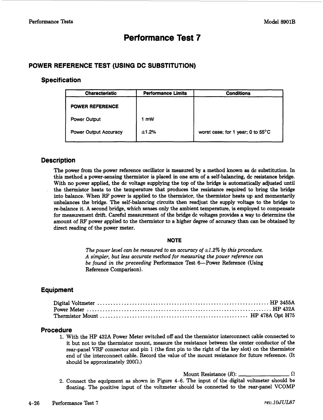
Characteristic
POWER REFERENCE
Power Output
Power Output Accuracy
Performance
Test
7
Performance Limits Conditions
1
mW
*l.2%
worst
case;
for
1
year;
0
to
55OC
POWER REFERENCE
TEST
(USING DC
SUBSTITUTION)
Specification
Description
The power from the power reference oscillator
is
measured
by
a method
known
as
dc substitution. In
this method
a
power-sensing thermistor
is
placed in one
arm
of a self-balancing, dc resistance bridge.
With no power applied, the dc voltage supplying the top
of
the bridge
is
automatically adjusted until
the thermistor heats
to
the temperature
that
produces the resistance required
to
bring the bridge
into balance. When
RF
power
is
applied
to
the thermistor, the thermistor heats up and momentarily
unbalances the bridge. The self-balancing circuits then readjust the supply voltage
to
the bridge
to
re-balance
it.
A
second bridge, which senses only the ambient temperature,
is
employed
to
compensate
for measurement
drift.
Careful measurement of the bridge dc voltages provides
a
way
to
determine the
amount of
RF
power applied
to
the thermistor
to
a higher degree of accuracy than can be obtained by
direct reading of the power meter.
NOTE
The power level can be measured to an accuracy of
*1.2%
by
this procedure.
A
simpler, but less accurate method for measuring the power reference can
be found in the preceeding
Performance Test 6-Power Reference (Using
Reference Comparison).
Equipment
Digital Voltmeter
.................................................................
HP 3455A
Power Meter
......................................................................
HP 432A
Thermistor Mount
........................................................
HP 478A Opt
H75
Procedure
1.
With the HP 432A Power Meter switched
off
and the thermistor interconnect cable connected
to
it
but not
to
the thermistor mount, measure the resistance between the center conductor of the
rear-panel VRF connector and pin
1
(the
first
pin
to
the right of the key slot) on the thermistor
end
of
the interconnect cable. Record the value of the mount resistance for future reference.
(It
should be approximately
2000.)
Mount Resistance
(R):
0
2.
Connect the equipment
as
shown in Figure 4-6. The input of the digital voltmeter should be
floating. The positive input
of
the voltmeter should be connected
to
the rear-panel VCOMP
4-26
Performance Test
7
reu.1
OJUL87

 Loading...


