Model 8901B
Characteristic
RF
POWER
Input
SWR
Performance
Tests
Performance
Limits
Conditions
<1.15
using
HP
11
722A
Sensor Module
Performance
Test
9
(SLaP
14)
SWR
TEST
Specification
DEVICE
INPUT
RF
REFLECTED
RF
OUTPUT
SPECTRUM ANALYZER
'
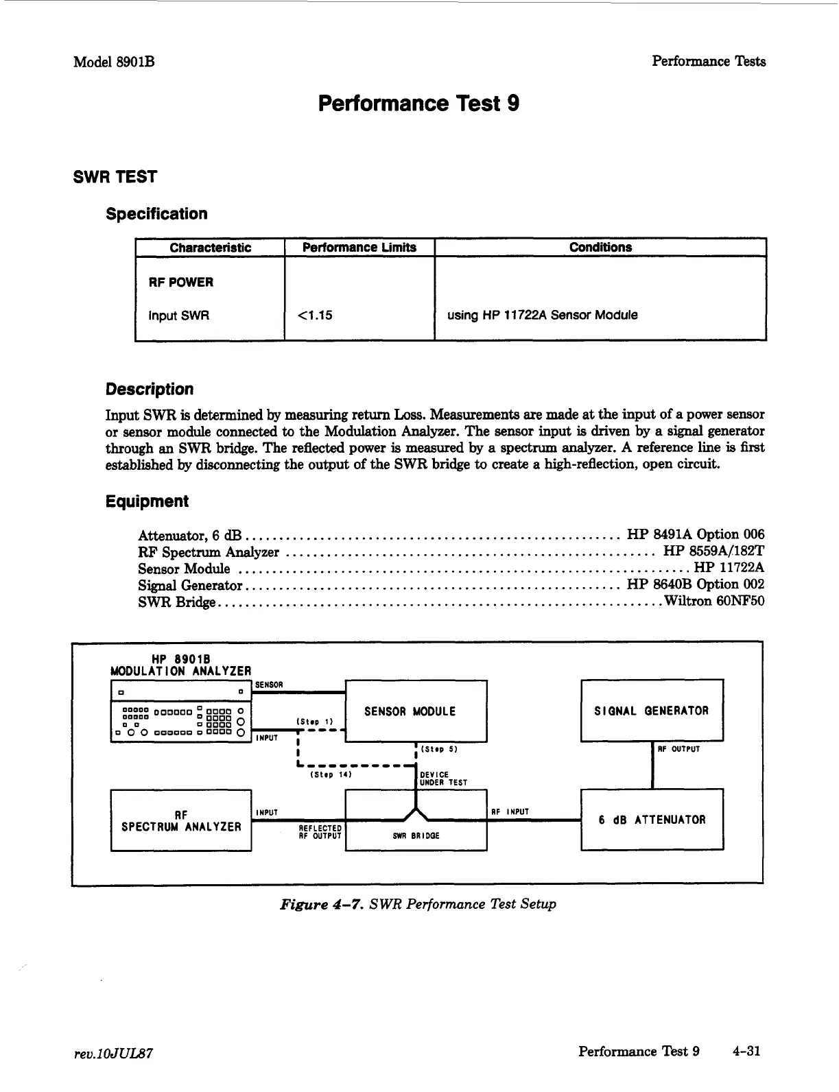
Description
Input
SWR
is
determined
by
measuring return
Loss.
Measurements
are
made
at
the input
of
a
power sensor
or sensor module connected
to
the Modulation Analyzer. The sensor input
is
driven by
a
signal
generator
through an SWR bridge. The reflected power
is
measured
by
a
spectrum analyzer. A reference line
is
first
established
by
disconnecting the output
of
the SWR bridge
to
create
a
high-reflection, open circuit.
RF
INPUT
6
dB
ATTENUATOR
SWR
BRIDQE
Equipment
Attenuator,
6
dB
.......................................................
HP
8491A Option
006
RF'
Spectrum Analyzer
......................................................
HP
8559AL182T
Sensor Module
..................................................................
HP 11722A
Signal
Generator.,
.....................................................
HP
8640B
Option 002
SWR
Bridge.
................................................................
Wiltron
60NF50
HP
89018
MODULATION ANALYZER
-
SENSOR
Lo
0
I
I
I
SIQNAL QENERATOR
I
I
RF
OUTPUT
I
I
Figure
4-7.
S
WR
Performance Test Setup
rev.1
OJUL87
Performance Test
9
4-31

 Loading...


