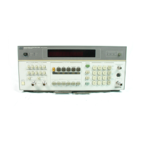
Performance
Tests
Performance
Test
10a
Model
890lB
30KHZ
(CELLULAR
RADIO)
ALTERNATE CHANNEL FILTER
-
OPTION
035
Description
Option
035
Performance Verification
This
test
is
to
be
performed on
Option030
instnune
nts
containing
Option
035
as
one
ofthe
alternate
channel
filters.
Inthis
test
anHP8662A(or level
~~ccu~acg
equivaleat altemative)
is
usedto
simulate
both
an
in-chanml
and
adjacent
channel
signal.
The
signal
generator
is
first
tuned
in-channel
60
that
the
reference
can
be
set
for
the
adjacent
channel
power
measurement.
The
signal
generator
is
thentunedto
the
adjacent
channel
and
the
LO
shjftedto
measure
the
signal
generator.
The
output
level of the
signal
generator
is
varied
to
exercise
Mmnt
combinations
of
IF
gain
Equipment
Signal
Generator..
. . . .
.
.
.
.
.
.
. .
.
. . .
. .
.
. .
. . .
.
. .
.
.
. .
.
.
. . . . .
.
.
.
.
.
.
. . .
. . . .
.
. .
. . . . . . .
.
.
. .
. . .
.
. .
. .
.
.
.
HP
8662A
Procedure
Initial Setup
1.
Set
the
signal
generator
to
150MHz
CW
at
0
dBm.
Connect
the
signal
generator output
to
the
Measuring Receiver's
RF'
Input. Allow
all
equipment
30
minute
warmup
minimum.
Filter Test
of
Option
030
Combination Which Includes Option
035
2.
On the Measuring Receiver, key
in
the following:
a.
41.0SP (Performs instrument PRESET)
b. 150
MHz
(Manually
tunes
the
LO)
c. 24.0SP (Initializes Option
030)
d. 24.1SP (Selects Option 035 filter, displays
IF
reference level value)
e.
30
kHz
UP
(Increments
LO
up
one
channel
spacing)
f. 24.2SP (Displays Option 035 filter ratio level value)
3. Offset the
signal
generator
Up
one channel spacing by incrementing fi.equency
30
Wz
(150.030
4.
Change signal generator power level to -75
dBm.
Read the
ratio
displayed on the Measuring
MHz).
The Measuring Receiver should display approximately
0
dB.
Receiver.
If
the display
is
slightly unstable due
to
noise, then average the readings.
LEVEL RATIO -75dB
(f1.5dB)
5.
Change signal generator power level
to
-65
dBm.
Read the
ratio
displayed on Measuring
Receiver.
LEVEL RATIO
-65dB
(fl.5dB)
6.
Change
signal
generator power level to
-45
dBm.
Read the
ratio
displayed
on
Measuring
Receiver.
LEVEL RATIO
-45dB
(f1.5dB)
7.
Change
signal
generator power level
to
-25
dBm.
Read the ratio displayed on Measuring
Receiver.
LEVEL RATIO -25dB
(k1.5d.B)
8.
Change signal generator power level
to
-10
dBm.
Read the ratio displayed on Measuring
Receiver.
LEVEL RATIO
-1OdB
(k1.5dB)
4-38
Performance Test
10a
reu.
01
OCT92

 Loading...