Performance Tests Model
8901B
Performance
Test
11
HIGH-SELECTIVITY GAIN (OPTION SERIES
030)
-
2642A AND ABOVE
Specification
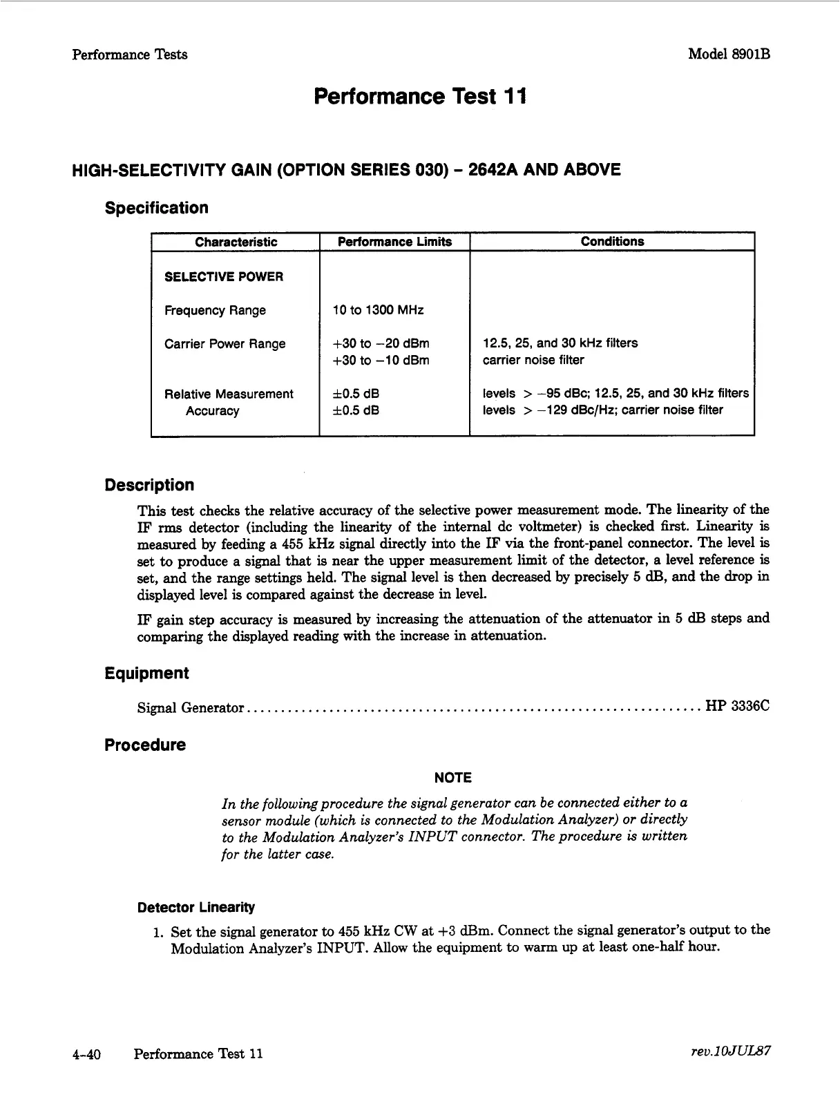
Characteristic
SELECTIVE
POWER
Frequency Range
Carrier Power Range
Relative Measurement
Accuracy
Performance
Limits
10
to
1300
MHz
t-30
to
-20
dBm
+30
to
-10
dBm
f0.5
dB
f0.5
dB
Conditions
12.5,
25,
and
30
kHz
filters
carrier noise filter
levels
>
-95
dBc;
12.5,
25,
and
30
kHz
filters
levels
>
-1
29
dBc/Hz; carrier noise filter
Description
This
test
checks the relative accuracy of the selective power measurement mode. The linearity
of
the
IF
rms
detector (including the linearity of the internal dc voltmeter)
is
checked
first.
Linearity is
measured by feeding a
455
kHz signal directly into the
IF
via the front-panel connector. The level
is
set
to
produce a signal
that
is
near the upper measurement limit of the detector, a level reference
is
set, and the range settings held. The signal level
is
then decreased by precisely
5
dB,
and the drop in
displayed level
is
compared against the decrease in level.
IF
gain step accuracy
is
measured by increasing the attenuation of the attenuator in
5
dB
steps and
comparing the displayed reading with the increase in attenuation.
Equipment
Signal Generator.
.
.
.
.
. .
.
.
.
.
. . .
. .
. . .
.
. . . . . . . .
. .
. . .
.
.
.
. . .
.
.
. .
.
.
.
. . .
.
.
.
. . . .
.
. . .
. .
.
. . .
HP
3336C
Procedure
NOTE
In the following procedure the signal generator can be connected either to a
sensor module (which
is
connected to the Modulation Analyzer)
or
directly
to the Modulation Analyzer’s INPUT connector. The procedure
is
written
for
the latter case.
Detector
Linearity
1.
Set the signal generator
to
455
kHz CW at
+3
am.
Connect the signal generator’s output to the
Modulation Analyzer’s INPUT. Allow the equipment to warm up at least one-half hour.
4-40
Performance Test
11
rev.lOJUI.87

 Loading...


