4. Thoroughly clean the thermal material from the surfaces of the heat sink and the system board
components each time the heat sink is removed. Replacement thermal material is included with the heat
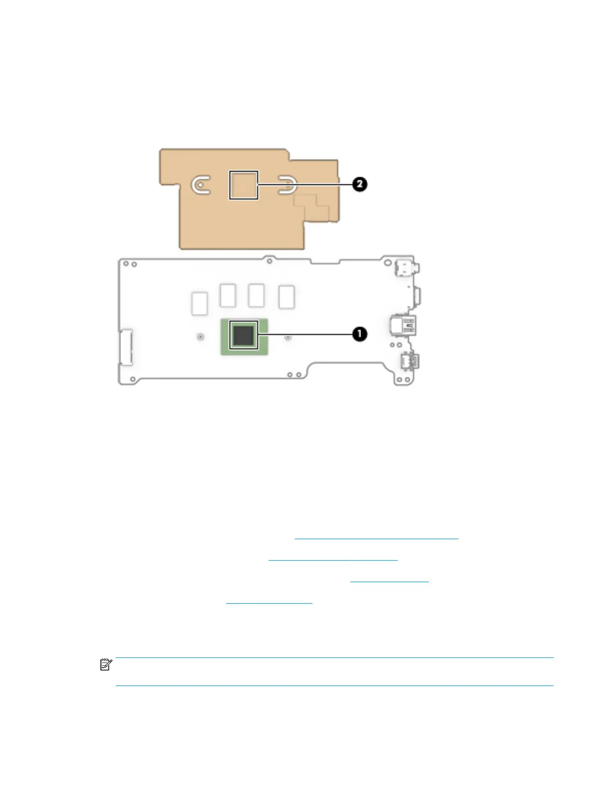
sink and system board spare part kits. The following illustration shows the replacement thermal material
locations.
Thermal paste is used on the processor (1) and the heat sink section (2) that services it.
Reverse this procedure to install the heat sink.
29.5 cm (11.6 in) display assembly
To remove and disassemble the display assembly, use these procedures and illustrations.
Full hinge-up displays are not available as spare parts. Spare parts for displays are available only at the
subcomponent level.
Before removing the display panel, follow these steps:
1. Prepare the computer for disassembly (see Preparation for disassembly on page 29).
2. Remove the top cover/keyboard (see Top cover/keyboard on page 29).
3. Disconnect the battery cable from the system board (see Battery on page 32).
4. Remove the speakers (see Speakers on page 34).
Remove the display assembly:
1. Disconnect the WLAN antenna cables (1) from the terminals on the WLAN module.
NOTE: The WLAN antenna cable labeled "1/MAIN" connects to the WLAN module "Main" terminal. The
WLAN antenna cable labeled "2/AUX" connects to the WLAN module "Aux" terminal.
2. Disconnect the display webcam/microphone cable (2) from the system board.
40 Chapter 5 Removal and replacement procedures for authorized service provider parts ENWW
 Loading...