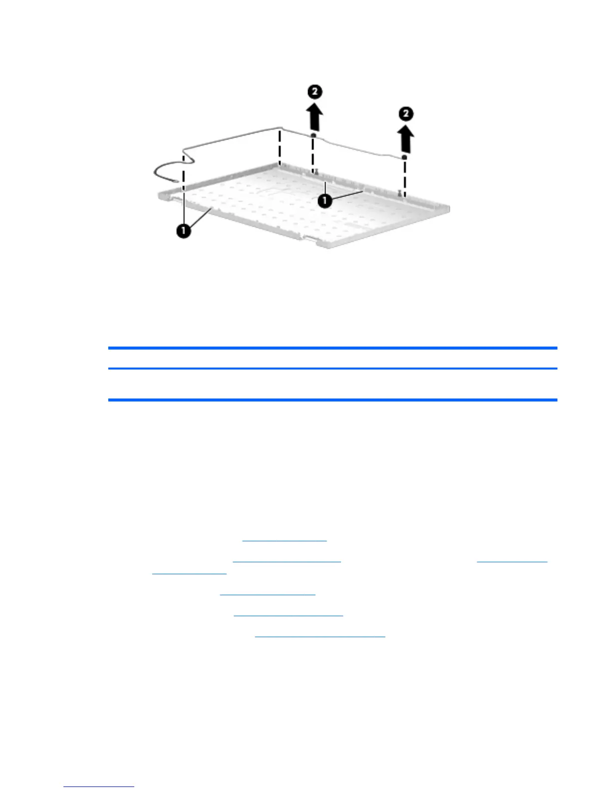
b. Release the microphone receivers (2) from the clips built into the display enclosure.
c. Remove the microphone receivers and cables. The microphone receivers and cables are
available using spare part number 596043-001.
Reverse this procedure to install the processor.
Top cover
Description Spare part number
Top cover (includes fingerprint reader board and cable, pointing stick buttons and cable, TouchPad
and cable)
597580-001
Before removing the top cover, follow these steps:
1. Shut down the computer. If you are unsure whether the computer is off or in Hibernation, turn
the computer on, and then shut it down through the operating system.
2. Disconnect all external devices connected to the computer.
3. Disconnect the power from the computer by first unplugging the power cord from the AC outlet
and then unplugging the AC adapter from the computer.
4. Remove the battery (see
Battery on page 46), and then remove the following components:
a. Optical drive (see
Optical drive on page 52) or secondary hard drive (see Secondary hard
drive on page 53)
b. Keyboard (see
Keyboard on page 61)
c. Switch cover (see
Switch cover on page 65)
d. Display assembly (see
Display assembly on page 74)
Remove the top cover:
1. Turn the computer upside down, with the front toward you.
2. Remove the eleven Torx T8M2.5×8.0 screws (1) that secure the top cover to the base
enclosure.
ENWW Component replacement procedures 83
 Loading...