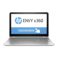
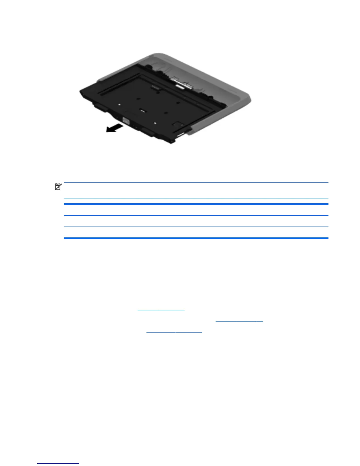
9. Remove the front cover by sliding it away from the Retail Jacket.
Reverse this procedure to install the front cover.
Bar code scanner module and Cable connector board
NOTE: The bar code scanner module and cable connector board spare part kits do not include the
respective cables. The cables are included in the Cable Kit, spare part number 744031-001.
Description Spare part number
Bar code scanner module 744037-001
Cable connector board 744034-001
Before removing the bar code scanner module and cable connector board, follow these steps:
1. Turn off the tablet. If you are unsure whether the tablet is off or in Hibernation, turn the tablet on, and
then shut it down through the operating system.
2. Disconnect the power from the tablet by unplugging the power cord from the tablet or the Retail Jacket.
3. Disconnect all external devices from the Retail Jacket.
4. Remove the top cap (see Top cap on page 63).
5. If installed, remove the tablet from the Retail Jacket (see Top cap on page 63).
6. Remove the front cover (see Front cover on page 65).
Remove the bar code scanner module and cable connector board:
1. Turn the front cover upside down with the top toward you.
2. Release the ZIF connector (1) to which the cable connector board cable is attached, and then disconnect
the cable connector board cable from the system board.
3. Detach the cable connector board cable (2) from the front cover. (The cable connector board cable is
attached to the front cover with double-sided adhesive.)
4. Remove the two Phillips PM1.3×3.0 screws (3) that secure the bar code scanner module to the front
cover.
5. Remove the two Phillips PM1.9×3.0 screws (4) that secure the cable connector board to the front cover.
Retail Jacket component replacement procedures 69
 Loading...