1-8
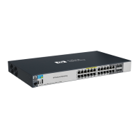
Introducing the Switch
Front of the Switch
Introducing the Switch
LED Mode Select Button and Indicator LEDs
The operation of the Mode LED is controlled by the LED Mode select button,
and the current setting is indicated by the LED Mode indicator LEDs near the
button. Press the button to step from one view mode to the next.
RPS Status
(green)
On
Blinking
Off
Normal operation. RPS is connected and operating correctly. RPS could be
powering the unit.
RPS is connected but has experienced a fault.
RPS is not connected or is not powered on.
EPS Status
(green)
On
Blinking
Off
Connected to an External Power Supply, and receiving power.
The External Power Supply is connected but has experienced a fault or is
unplugged.
The switch is not connected to an EPS.
Fan Status
(green)
On
Blinking
1
Normal operation, all fans are ok.
One of the unit’s fans has failed. The switch Fault LED will be blinking simultaneously.
PoE Status On
Off
Blinking
1
Blinking
2
If any ports are supplying PoE power.
If no ports are supplying PoE power. Should be off only during the boot process.
If any port has a internal hardware failure
If any port is denied PoE power or detecting an external PD fault
Temp
(green/Orange)
Off Switch temperature is normal.
Blinking
1
An over temperature condition has been detected.
Auxiliary (green/
orange) For more
information see
the Management
and Configuration
Guide for your
switch.
Blinking
green
1
Indicates the switch is processing a USB command file.
On green The switch has finished processing the USB command file successfully.
Blinking
orange
2
Indicates an error condition.
Off Indicates that no USB device has been inserted, or that the inserted USB device
cannot be recognized, or that no command file can be found on the inserted USB
device.
1
The blinking behavior is an on/off cycle once every 1.6 seconds, approximately.
2
The blinking behavior is an on/off cycle once every 0.8 seconds, approximately.
Switch LEDs State Meaning
 Loading...