1-11
Introducing the Switch
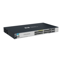
Front of the Switch
Introducing the Switch
Console Port
This port is used to connect a console to the switch by using the RJ-45 to DB9
cable, supplied with the switch. This connection is described under “Connect
a Console to the Switch” in chapter 2, “Installing the Switch.” The console can
be a PC or workstation running a VT-100 terminal emulator, or a VT-100
terminal.
Expansion Module LEDs
“Expansion Module” LEDs refer to the LEDs specific to the expansion module.
These LEDs are located on the physical expansion module bulkhead. These
LEDs are only viewable in the rear of the Switch 2910al-48G product on the
Expansion Slot Module itself.
Table 1-3. Expansion Module LEDs
Expansion module LEDs operate in modes for Link and Mode. FDx and Spd modes
have no meaning for the 10-GbE ports on the expansion module.
Name Color Mode Description
Expansion Module LEDs per module
Module
Status
Green/
Orange
On green
Off
Blinking
orange
Expansion module is plugged into expansion slot and operating correctly
Expansion module's power has been turned OFF, and the card can be
removed from the box if necessary.
Expansion module is plugged into expansion slot but has experienced a
fault. Flashes simultaneously with the Fault LED.
Expansion Module LEDs per port
Link Green/
Orange
On green
Off
Blinking
orange
Indicates that the port LEDs are displaying link information:
• if the port LED is on, the port is enabled and receiving a link indication
from the connected device.
• if the port LED is off, the port has no active network cable connected,
or is not receiving link beat or sufficient light. Otherwise, the port may
have been disabled through the switch console, the web browser
interface, or ProCurve Manager.
• if the port LED is blinking
1
simultaneously with the Fault LED, the
corresponding port has experienced a hardware failure or has failed
its self test.
Mode Green On The operation of the Mode LED is controlled by the LED Mode select
button, and the current setting is indicated by the LED Mode indicator
LEDs near the button. Press the button to step from one view mode to the
next. The default view is Activity (Act). See page 7.
1
The blinking behavior is an on/off cycle once every 1.6 seconds, approximately.
 Loading...