2-4
Installing the Switch
Installation Procedures
Installing the Switch
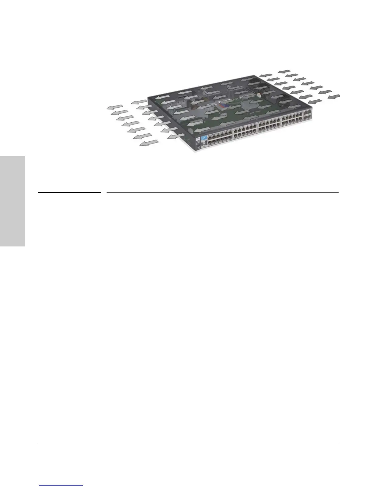
Figure 2-1. Air flow direction of the 2910al switch
Installation Procedures
Summary
1. Prepare the installation site (page 2-5). Ensure the physical environ-
ment is properly prepared, including having the correct network cabling
ready to connect to the switch and having an appropriate location for the
switch. See page 2-3 for some installation precautions.
2. Verify the switch passes self test (page 2-11). Plug the switch into a
power source and observe that the LEDs on the switch’s front panel
indicate correct switch operation. When self test is complete, unplug the
switch.
3. (Optional) Install a module (page 2-8).
4. Mount the switch (page 2-11). The Switch can be mounted in a 19-inch
telco rack, in an equipment cabinet, or on a horizontal surface.
5. (Optional) Install a transceiver (page 2-14). If you have installed a
module, you can now install one or two transceivers.
6. (Optional) Install mini-GBICs and SFPs (page 2-16). The switch has
four slots for installing mini-GBICs. Depending on where you will mount
the switch, it may be easier to install the mini-GBICs first. Mini-GBICs can
be installed or removed while the switch is powered on.
7. Connect power to the switch (page 2-18). Once the switch is mounted,
plug it into the nearby main power source.
8. (Optional) Connect an external power supply page 2-18
 Loading...