Component replacement procedures
This chapter provides removal and replacement procedures.
There are as many as 33 screws, in 3 different sizes, that must be removed, replaced, or loosened
when servicing the computer. Make special note of each screw size and location during removal and
replacement.
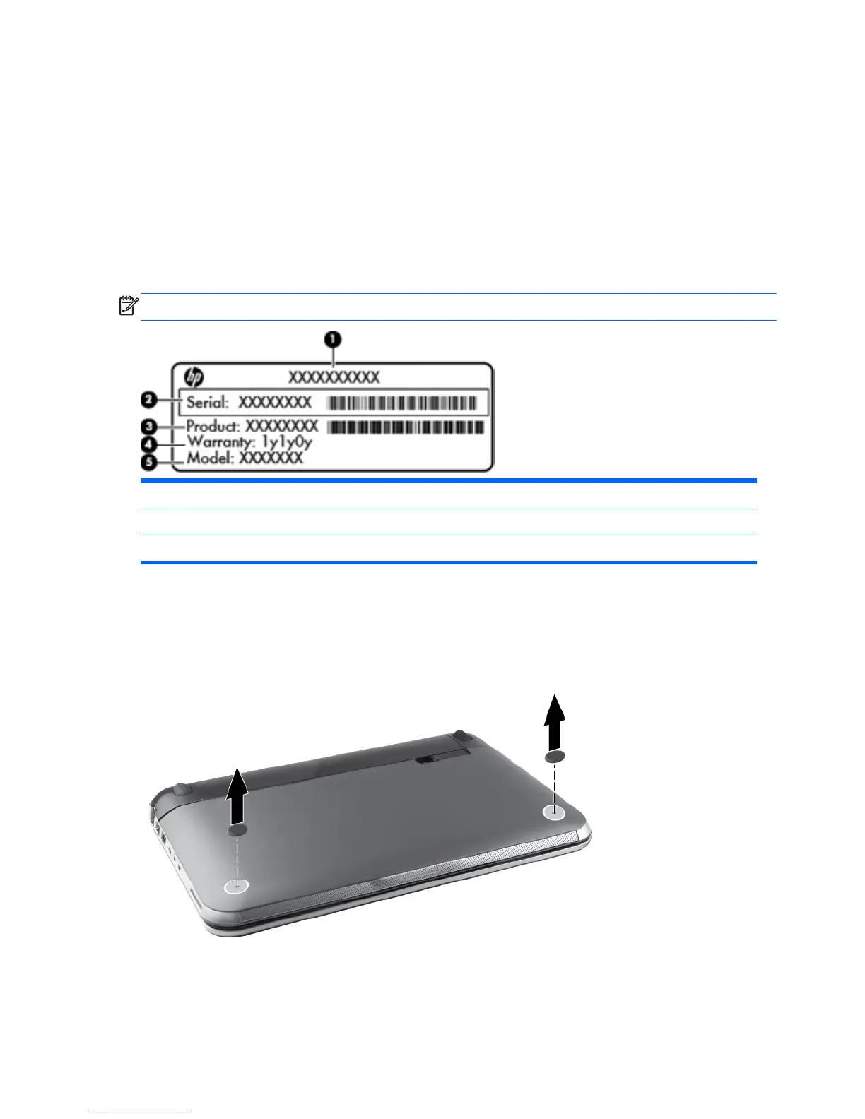
Service tag
When ordering parts or requesting information, provide the computer serial number and model
number provided on the service tag, located inside the battery bay.
NOTE: Serial number label location, format, and color vary on select models.
(1) Product name (4) Warranty period
(2) Serial number (5) Model description (select models)
(3) Product number
Computer feet
The computer feet are adhesive-backed rubber pads. The feet are included in the Rubber Kit, spare
part number 650734-001. There are 2 rubber feet that attach to the base enclosure in the locations
shown in the following illustration.
36 Chapter 4 Removal and replacement procedures
 Loading...