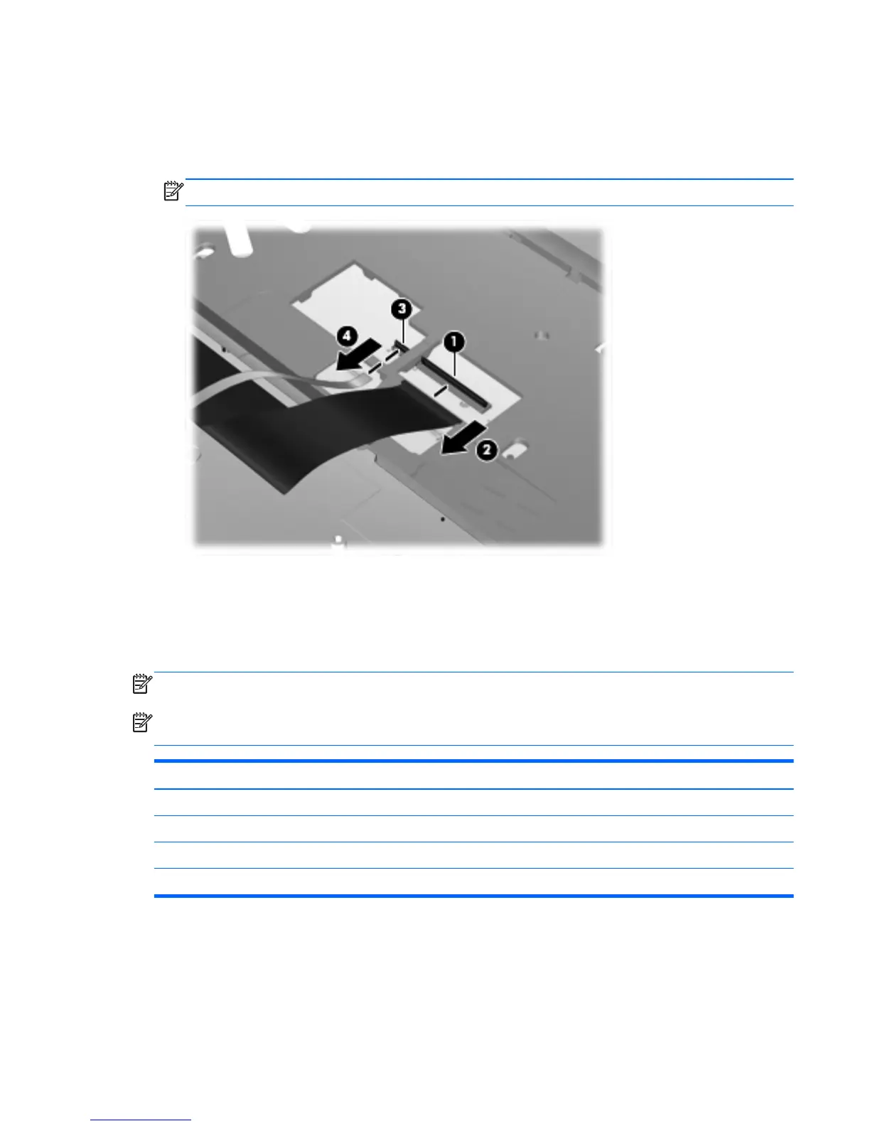
8. Lift the keyboard connector latch (1), and then disconnect the keyboard cable from the system
board (2).
9. If applicable, lift the pointing stick connector latch (3), and then disconnect the pointing stick
cable from the system board (4).
NOTE: Some models are not equipped with a pointing stick.
10. Remove the keyboard.
Reverse this procedure to install the keyboard.
Bottom cover
NOTE: The bottom covers includes rubber feet.
NOTE: Make sure to remove the modem plug from the slot in the bottom cover if the repaired unit
includes a modem.
Description Spare part number
Bottom cover 644695-001
Top cover for use on models that include a fingerprint reader, without a pointing stick 641204-001
Top cover for use on models that include a fingerprint reader and a pointing stick 641205-001
Top cover for use on models that include a pointing stick, without a fingerprint reader 641206-001
Component replacement procedures 73
 Loading...