4-15
Planning and Implementation for the Series 5400zl Switch
Planning Your PoE Configuration
Planning and
Implementation for the
Series 5400zl Switch
Standard J8713A Configurations
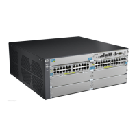
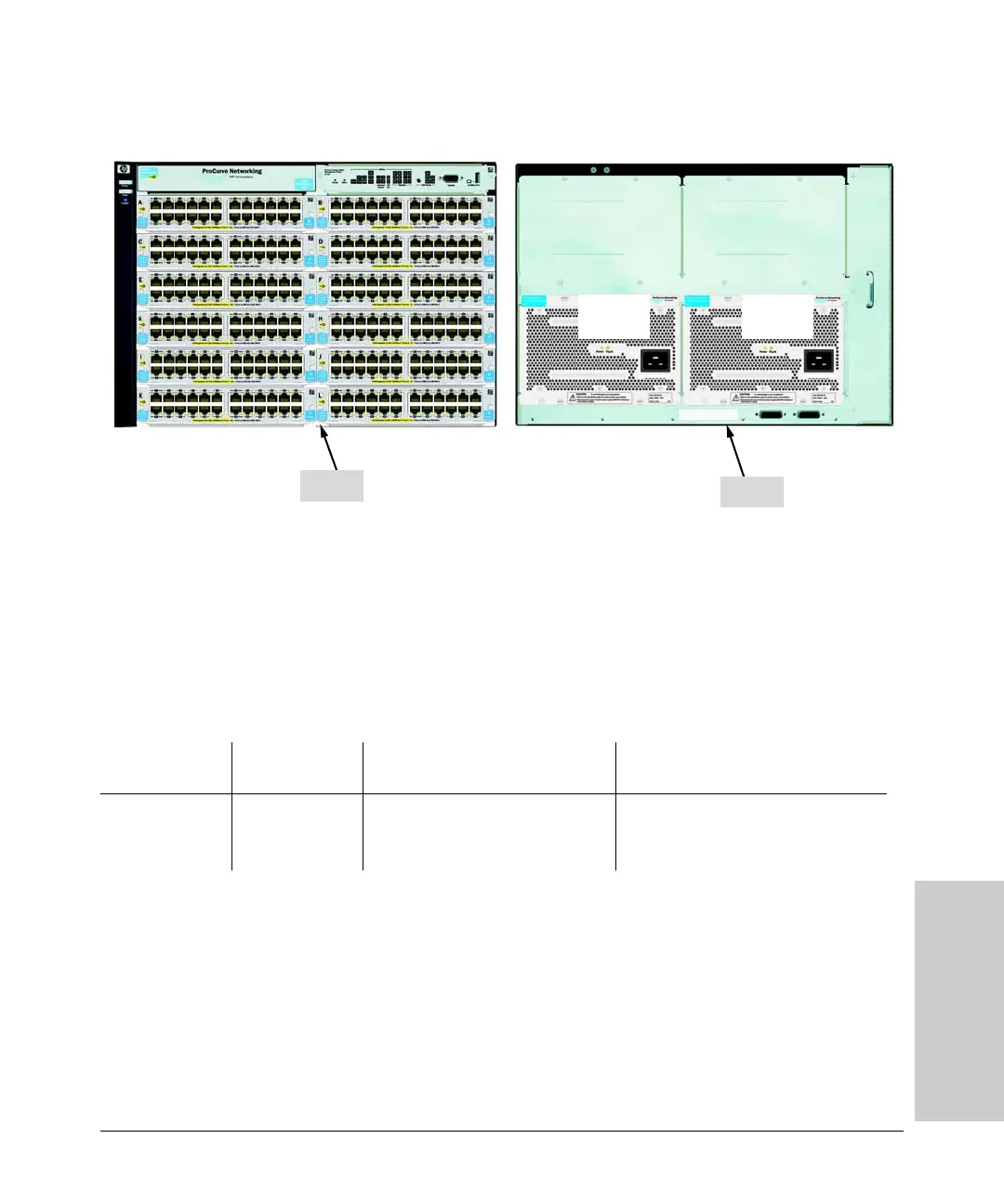
Figure 4-11. Example of a 5412zl with two power supplies, J8713A
This configuration is an example of two power supplies supplying 900 watts
each for a maximum of 1800 watts to a fully loaded chassis of 288 ports.
Therefore out of the total 288 available ports, 116 can be powered at 15.4 watts
each. That’s equal to a little over 4 modules. Or all ports could be used at 4.0
watts.
Or, 55 ports could be provisioned at 15.4 watts using 847 watts of the total 1800
leaving 953 watts. Then provision the other 238 ports at 4 watts using 952 watts
of the remaining 953 watts. Finally leaving 1 watt.
This configuration could be redundant for PoE power up to 900 W. The upper
6 slots would stay up if they were the ports suppling the PoE power and the
lower 6 slots were used for other than PoE power. One power supply has
enough power to supply system power to the upper 6 slots and keep the switch
up and running. And as long as the 900 watts of PoE power is not exceeded,
then the top 6 modules would remain powered.
Back
Front
900 Watts
for PoE
900 Watts
for PoE
Source of Power Watts Available # of Ports Powered and Average
Watts/Port
Redundant # of Ports Powered and
Average Watts/Port
Two Internal PoE
Power Supplies
(J8713A)
1800 (without
redundancy)
• 116 @ average 15.4 W each
• 257 @ average 7.0 W each
• 288 @ average 4.0 W each
•None
 Loading...