14 TippingPoint 10 Overview
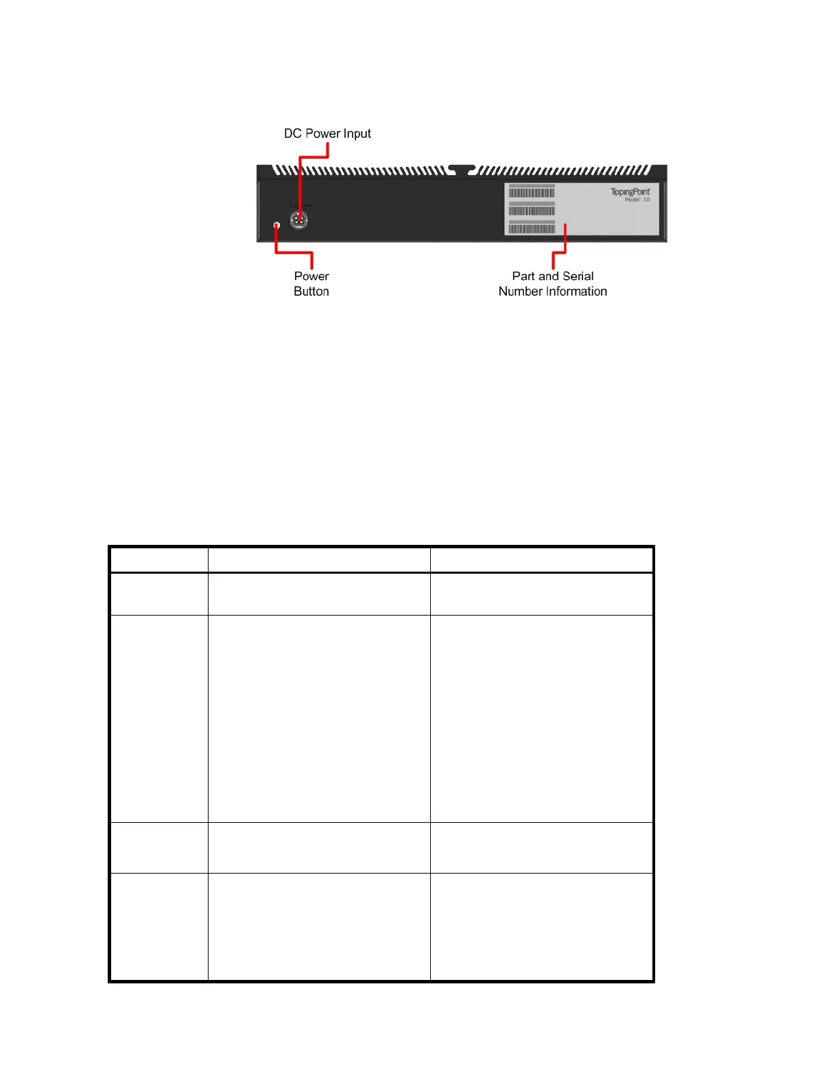
Figure 3-2 shows the chassis back panel for a TippingPoint 10.
The TippingPoint 10 ships with the following pre-installed components:
• Two 10/100/1000 Gigabit Ethernet segments supporting up to 20 Mbps aggregate across all
segments
• One 10/100/1000 Gigabit Ethernet management port
• One serial console RJ-45 port (Pinout: 1-RTS, 2-DTR, 3-TXD, 4-GND, 5-GND, 6- RXD, 7-DSR, 8-CTS)
• Two USB ports
LEDs
The following table describes the status LEDs used by the TippingPoint 10.
Figure 3-2 TippingPoint 10 - Back Panel
Table 3-1 TippingPoint 10 LEDs
LED Location Description
Power The right side of the front panel. Green: Indicates that the device has
power and is running.
Status The right side of the front panel,
above the Power LED.
Off: No power
Yellow: Device is booting OR one of
the following faults has occurred:
• A Critical or Error event in the
system log
• A thermal, memory, or disk alert
• High availability failover status
due to another event
Green: The device is running
normally.
Link The right side of each RJ45 port. Green: The link on the port is active.
No light: The link is down.
Packet Activity The left side of each RJ45 port. Flashing Yellow: The port is passing
data.
Solid Yellow: Link is present, but
there is no packet activity.
No light: No data is passing.
 Loading...