TippingPoint 10/110/330 Hardware Installation and Safety Guide 29
A Connector and Pinout Specifications
This appendix provides connector and pinout information for the TippingPoint system. This appendix
contains the following sections:
• ”RJ-45 (COM) Console” on page 29
• ”RJ-45 Ethernet Connectors” on page 29
RJ-45 (COM) Console
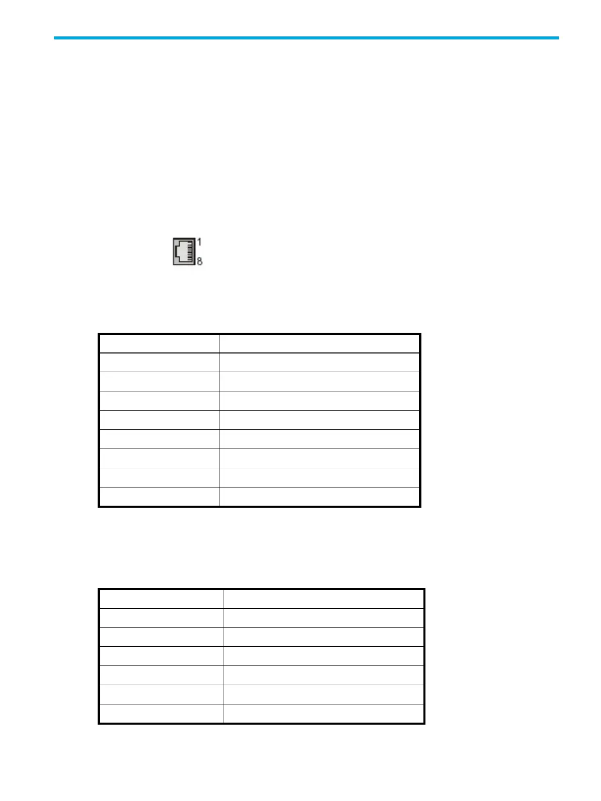
The following figure displays the RJ-45 connector.
Table A-1 shows the RJ-45 console connector pinouts.
RJ-45 Ethernet Connectors
Use the following pinout information when your RJ-45 device is operating in 10Mbps/100Mbps mode.
Figure A-1 RJ-45 Connector
Table A-1 RJ-45 Console Connector Pinouts
Pin Number Signal Name
1Request to Send (RTS)
2 Data Terminal Ready (DTR)
3 Transmit Data (TxD)
4Ground (GND)
5 Ground (GND)
6 Receive Data (RxD)
7 Data Set Ready (DSR)
8 Clear to Send (CTS)
Table A-2 RJ-45 Ethernet Connector Pinouts
Pin Number Signal Name
1 Transmit positive (Tx+)
2 Transmit negative (Tx-)
3 Receive positive (Rx+)
4Ground (GND)
5Ground (GND)
6Receive negative (Rx-)
 Loading...