2. Lift the J4 connector from the PCB.
3. Place the new component on the PCB. Be sure that it matches the PCB footprint
4. Solder the new component.
USB connector J5
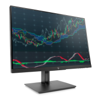
1. Use a hot air gun to melt the solder on the pins. Pin solder with soldering iron and absorber. You
can gently push down with the soldering iron once everything is molten to move the J5 out of the
through holes.
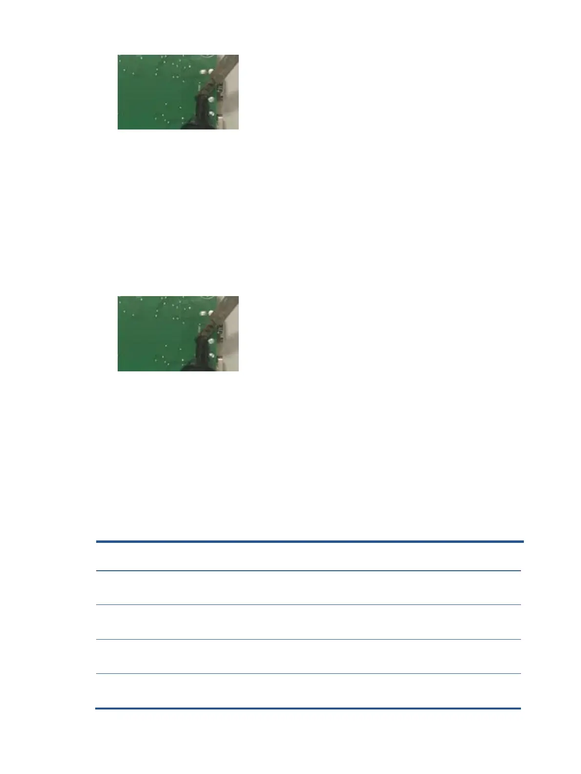
2. Lift the J5 connector from the PCB.
3. Place the new component on the PCB. Be sure that it matches the PCB footprint
4. Solder the new component.
Function test
After repair, be sure to confirm that all functions are working.
Function test
After repair, be sure to confirm that all functions are working.
Table 4-1: Function test
Confirm whether image displays and sound
plays correctly on the monitor.
Confirm whether image displays and sound
plays correctly on the monitor.
Change volume and balance to confirm whether
volume is smooth and loud enough.
Confirm whether image displays and sound
plays correctly on the monitor.
Confirm whether image displays and sound
plays correctly on the monitor.
Change volume and balance to confirm whether
volume is smooth and loud enough.
Confirm whether image displays and sound
plays correctly on the monitor.
 Loading...