lp-505 Rev. 000 Rel. 015 Date 1.7.20
20
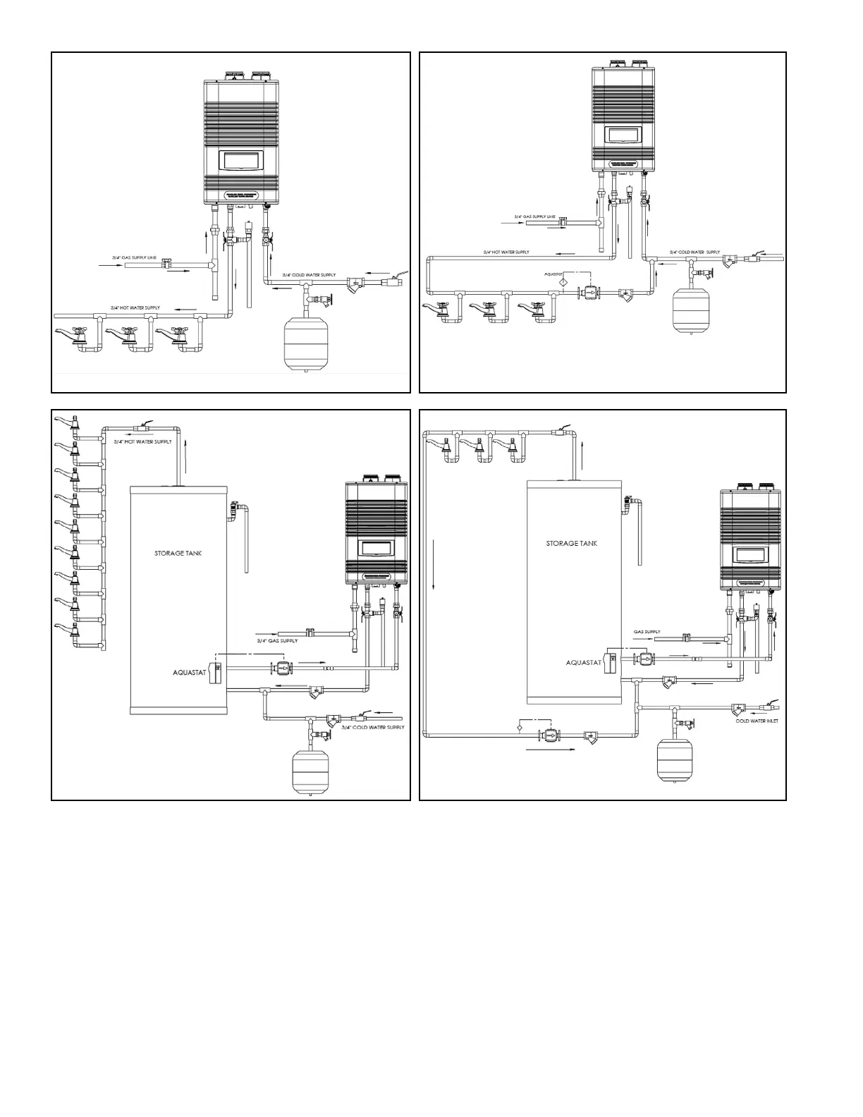
NOTES:
1. Minimum pipe size should match connection size. Upsize pipe accordingly if greater ow is required.
2. A thermal expansion tank suitable for potable water must be sized and installed within this piping system between the backow preventer
and the cold water inlet.
3. All circulators should have an integral ow check.
4. Drains and check valve between water heater and piping will assist in purging air from system.
5. These drawings are meant to demonstrate system piping only. The installer is responsible for all equipment and detailing required by local
codes. In Massachusetts, you must install a vacuum relief valve per 248 CMR.
6. Mixing valve application is optional, but recommended to help prevent scalding.
7. Always shut o power to the water heater or isolate the heater from the system if ANY plumbing work is to be done. Running the water
heater without water will result in dry-ring.
8. When using unit with storage tank, the setpoint of the water heater needs to be at least 20
o
F higher than the setpoint of the Aquastat on
the tank. Pump selection must meet a minimum ow rate requirement of 2 GPM.
NOTE: These drawings are meant to show system piping concept only. Installer is responsible for all equipment and detailing required by
local codes.
Figure 8 - DHW Piping, Single Water Heater
Figure 9 - DHW Piping, Single Water Heater with Recirculation
Figure 10 - DHW Piping with Storage Tank
Figure 11 - DHW Piping with Storage Tank and Recirculation
 Loading...