When Select a 24K Indoor Unit
The 24K indoor unit can only be connected with
an A system. If there are two 24K indoor units,
they can be connected with A and B systems.
(See Fig. 6.10)
Fig. 6.10
Table 6.3: Connective pipe size of an A and B
system (unit: inch)
Indoor Unit capacity
(Btu/h)
Liquid Gas
7K/9K/12K 1/4 3/8
12K/18K 1/4 1/2
24K 3/8 5/8
NOTE:
The minimum distance between the
outdoor unit and walls described in the
installation guide does not apply to airtight
rooms. Be sure to keep the unit unobstructed
in at least two of the three directions (M, N, P)
(See Fig. 6.8)
Fig. 6.8
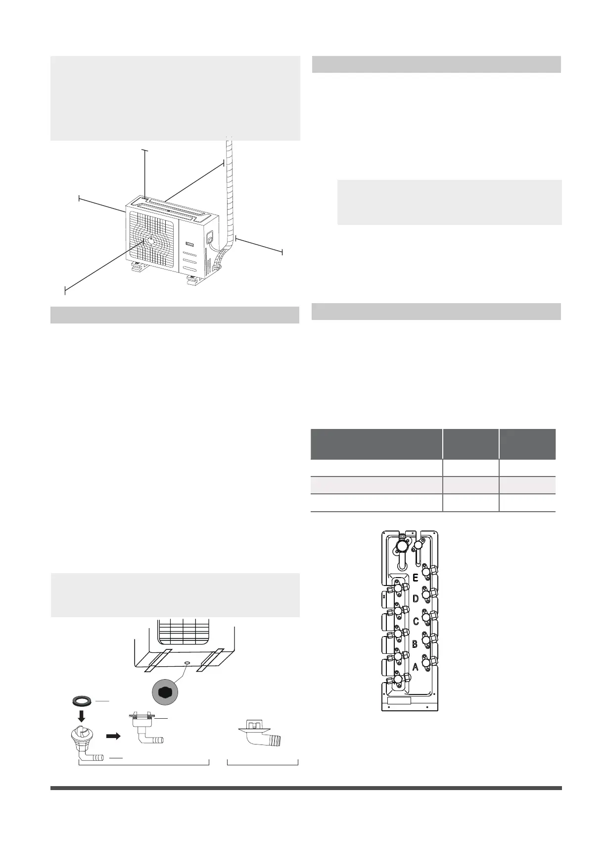
Drain Joint Installation
Notes On Drilling Hole In Wall
You must drill a hole in the wall for the
refrigerant piping, and the signal cable that will
connect the indoor and outdoor units.
1.
Determine the location of the wall hole
based on the location of the outdoor unit.
2.
Using a 65-mm (2.5”) core drill, drill a hole
in the wall.
NOTE: When drilling the wall hole, make
sure to avoid wires, plumbing, and other
sensitive components.
3.
Place the protective wall cu in the hole.
This protects the edges of the hole and
helps seal it when you nish the installation
process.
M
N
P
30 cm / 11.8” from back wall
60 cm / 23.6” above
30 cm / 11.8” on left
200 cm / 78” in front
NOTE: Make sure the water drains to a safe
location where it will not cause water damage
or a slipping hazard.
Seal
Drain joint
(A) (B)
Base pan hole of
outdoor unit
Seal
Fig. 6.9
If the drain joint comes with a rubber seal
(see Fig. 6.9 - A ), do the following:
1. Fit the rubber seal on the end of the drain joint
that will connect to the outdoor unit.
2. Insert the drain joint into the hole in the base
pan of the unit.
3. Rotate the drain joint 90° until it clicks in place
facing the front of the unit.
4. Connect a drain hose extension (not included)
to the drain joint to redirect water from the
unit during heating mode.
If the drain joint doesn’t come with a rubber
seal (see Fig. 6.9 - B ), do the following:
1. Insert the drain joint into the hole in the base
pan of the unit. The drain joint will click in
place.
2. Connect a drain hose extension (not included)
to the drain joint to redirect water from the
unit during heating mode.
 Loading...