English – 15
Repair instructions
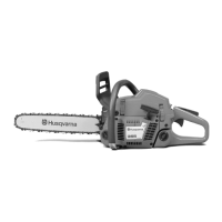
Stop switch – removal
1
Remove the cylinder cover and air filter.
2
Disconnect both leads from the stop plate and stop
switch. Remove the stop plate by carefully sliding it
over the lug on the front mounting.
3
Carefully prise the carburettor assembly off the left-
hand rubber mounting using a small screwdriver.
4
Carefully prise the stop switch’s upper mounting off
the air filter holder while lifting the switch to release
it from the lower mounting.
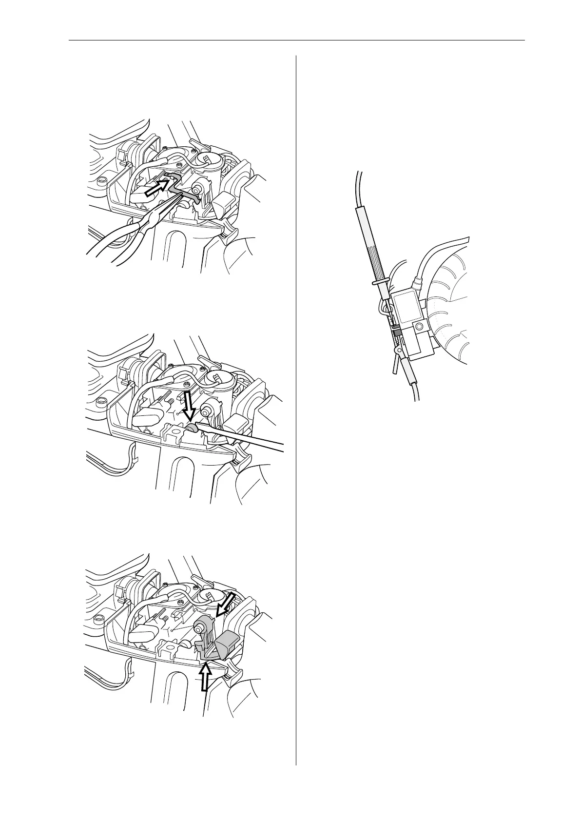
Measure the resistance by connecting a multimeter
to the ignition coil. NOTE! The switch must be in
the “on” position to give the correct reading.
The resistance must not be higher than 0.2 ohm
when the switch is in the on position.
Stop switch – resistance measurement
Clean the mating surfaces and check the resist-
ance as follows:
Cleaning and inspection
Clean and inspect all parts carefully. If there are
any cracks or other defects replace the damaged
parts with new ones. Always use original parts.
For Husqvarna Parts Call 606-678-9623 or 606-561-4983
www.mymowerparts.com
 Loading...