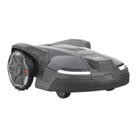
products are paired to the rest of the fleet by using the
Automower
®
Connect app in conjunction with the
Husqvarna Fleet Services
™
app, which is available at
AppStore and GooglePlay. There is more information
about Husqvarna Fleet Services
™
and how to subscribe
to the services on www.husqvarna.com.
3.13 Test docking with the charging station
Before using the robotic lawnmower, check that the
robotic lawnmower can follow the guide wire all the way
to the charging station and easily docks with the
charging station.
The test function is found in the robotic lawnmower’s
Installation
>
Find charging station
>
Guide
>
More
>
Test guide
menu. For more information, see
Boundary >
More > Test right / Test left on page 30
.
If no guide wire is installed the test should be carried out
on the boundary wire, both clockwise and anti-
clockwise.
The guide system must first be calibrated if the above
test is to provide a satisfactory result. See
First start-up
and calibration on page 19
.
3.14 Control panel
3.14.1 Control panel
All commands and settings for the robotic lawnmower
are done on the control panel. The control panel
consists of a display and a keypad. All information is
shown on the display and all input is done using the
buttons.
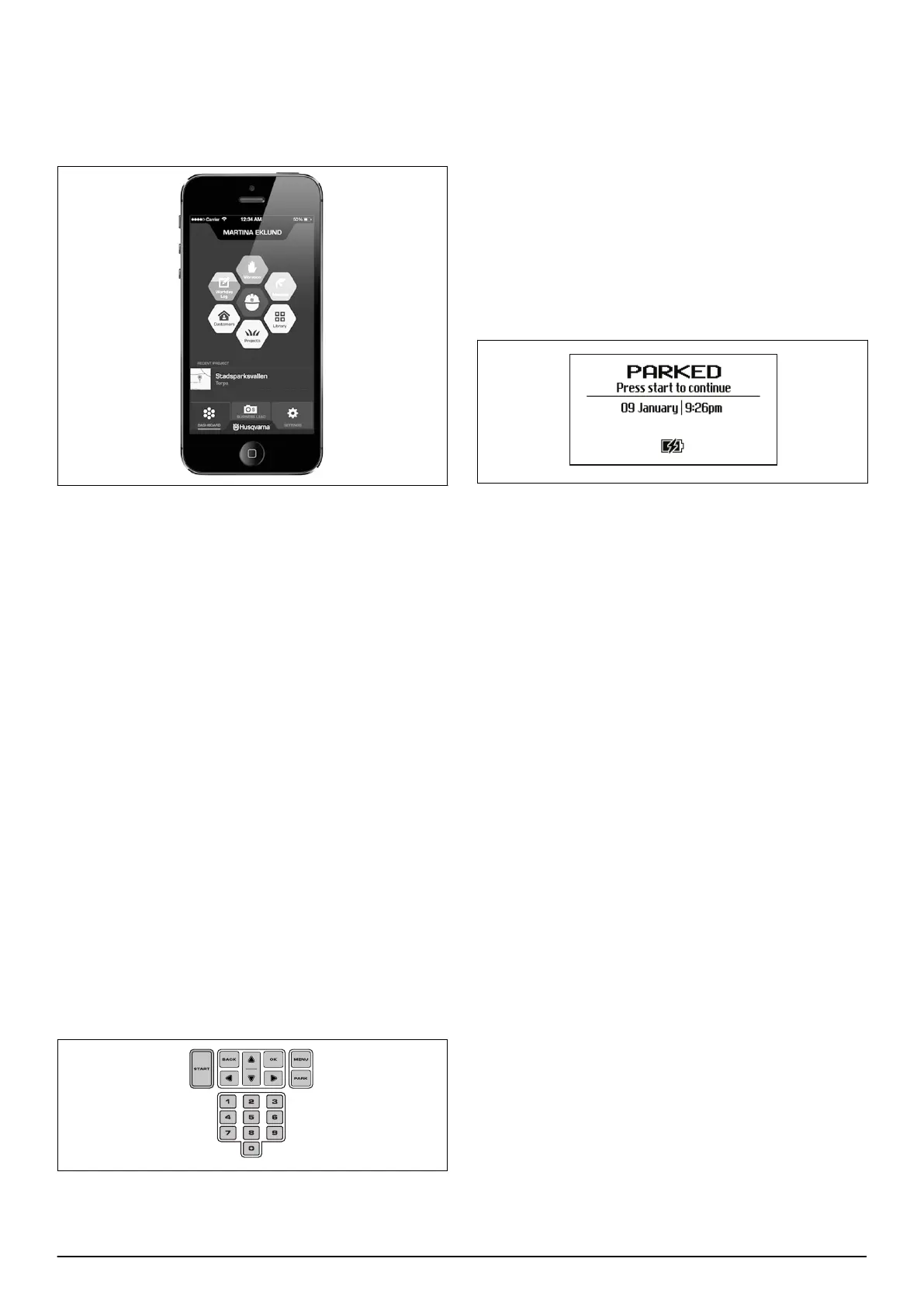
3.14.2 Keypad
The keypad consists of 6 groups of buttons:
• The START button is used to activate the robotic
lawnmower. This is normally the last button to be
pressed before closing the hatch.
• The BACK and OK buttons are used to navigate in
the menu. The OK button is also used to confirm
settings.
• The arrow keys are used to navigate in the menu but
also to make selections in certain setting options.
• The MENU button is used to go to the main menu.
• The PARK button is used to send the robotic
lawnmower to the charging station.
• The number keys are used to enter settings, for
example PIN code, time or exit direction.
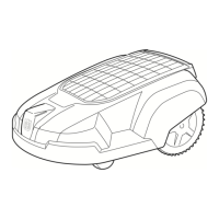
3.14.3 Display
When the STOP button has been pressed and the hatch
is opened, the display is showing the following
information:
• Operating information, e.g.
MOWING, PARKED
or
TIMER
. If the stop button is pressed when the
robotic lawnmower is running, what it did just before
it was stopped e.g.
MOWING
or
SEARCHING
is
displayed. The text READY is displayed if the robotic
lawnmower is not in any specific operating mode,
e.g. if the main switch has just been turned on.
• Date and clock show the current time:
3.14.4 Symbols shown on the display
The black clock symbol (A) indicates when the mower is
not allowed to mow due to a timer setting. If the mower
is not allowed to mow due to Weather timer, symbol (B)
is shown (not applicable for Automower
®
310). If the
operation mode Override timer is chosen, symbol (C) is
shown.
The battery status shows the remaining battery charge.
If the robotic lawnmower is loading, a flash is also
shown over the battery symbol (D). If the robotic
lawnmower is placed in the charging station without
charging, (E) is shown.
The ECO symbol (F) is displayed if the robotic
lawnmower is set in
ECO mode
.
Below symbols are valid for Automower
®
315X:
The satellite symbol is shown when GPS assisted
navigation is enabled. Symbol (G) is displayed when the
robotic lawnmower has established contact with a
sufficient number of GPS satellites. Symbol (H) is
displayed if the robotic lawnmower does not have
contact with a sufficient number of satellites. Symbol (G)
flashes during the first days the robotic lawnmower is
working as it gathers GPS information concerning the
installation
With Automower
®
Connect activated, additional symbols
(I, J, K) are displayed on the product's display:
The bars show the signal strength of the GPRS
reception. An X next to the bars indicates that there is
22 - Installation 840 - 001 -

 Loading...