604220 3-1 REV U
OPERATION
Safe Operating Practices
Refer to the Safety Precautions section of this manual for
operational and personal safety information.
Control Panel
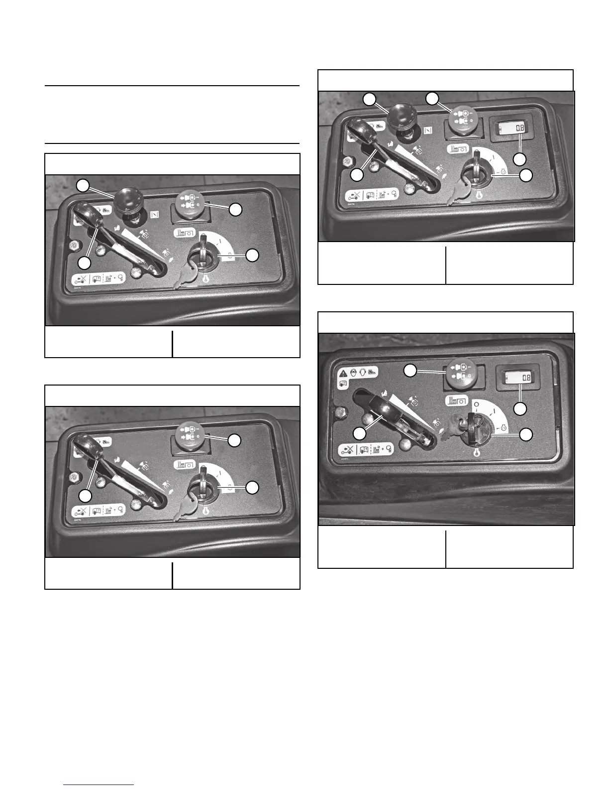
A. Deck clutch switch (Figure 3-1, Figure 3-2, Figure 3-3 &
Figure 3-4) — this switch engages the deck. Pull the
switch up to engage and push the switch down to dis-
engage the clutch.
For additional clutch information refer to the Mower
Deck Operation section of this manual.
B. Ignition switch (Figure 3-1, Figure 3-2, Figure 3-3 &
Figure 3-4) — a three position switch: “OFF”, “RUN”,
and “START”. With the key inserted, rotate it clockwise
to the “START” position; release the key when the
engine starts, and the switch will automatically return
to the “RUN” position
C. Throttle control (Figure 3-1, Figure 3-2, Figure 3-3 &
Figure 3-4) — a cable is linked to the engine throttle for
controlling engine speed. Move the lever forward to
increase engine rpm, move the lever rearward to
decrease engine rpm.
D. Choke control (Figure 3-1 & Figure 3-3) — a cable is
linked to manually operate the engine choke. When the
lever is in the down position, the choke is in the “OFF”
(run) position. When the knob is pulled up, the choke is
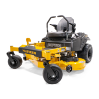
Raptor with Kawasaki engines
A. Deck clutch switch
B. Ignition switch
C. Throttle
D. Choke
Figure 3-1
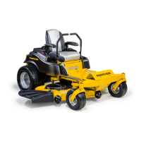
Raptor with Kohler or Briggs & Stratton engines
A. Deck clutch switch
B. Ignition switch
C. Throttle
D. N/A
Figure 3-2
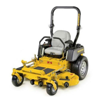
Raptor Limited with Kawasaki engines
A. Deck clutch switch
B. Ignition switch
C. Throttle
D. Choke
E. Hour meter
Figure 3-3
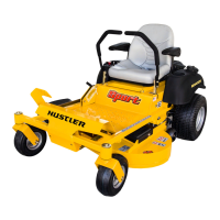
Raptor Limited with Kohler engines
A. Deck clutch switch
B. Ignition switch
C. Throttle
D. N/A
E. Hour meter
Figure 3-4
 Loading...