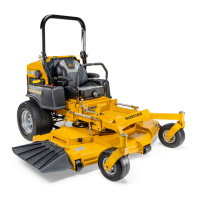
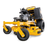
Introduction
Your Super Mini Z was adjusted before it left the factory and was
checked during predelivery setup. However, after start-up and continued
use, a certain amount of break-in wear will cause some adjustments to
change.
Remain alert for unusual noises, they could be signaling a problem.
Visually inspect the machine for any abnormal wear or damage. A good
time to detect potential problems is while performing scheduled
maintenance service. Correcting the problem as quickly as possible is the
best insurance.
Clear away heavy build-up of grease, oil and dirt, especially in the area
of reservoir and oil and engine combustion air; minute dust particle are
abrasive to close-tolerance engine and hydraulic assemblies.
Some repairs require the assistance of a trained service mechanic and
should not be attempted by unskilled personnel. Consult your Hustler
service center when assistance is needed.
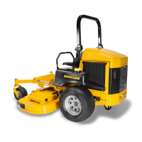
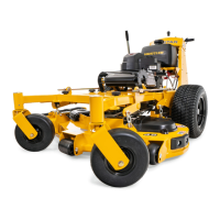
Steering linkage
The neutral adjustment for the control levers in the neutral position is
discussed in this section.
The tractor steering has been factory adjusted to eliminate creeping
when the control levers are in the neutral position (Fig. 11-19). However,
should the tractor begin to creep, the control lever linkage can be adjusted
as follows:
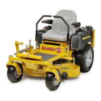
Control Lever Neutral Adjustment
Before considering any adjustment, check the tire air pressure and make
certain hydraulic system oil is at operating temperature. Unequal tire
pressure will cause the tractor to drift to one side. Refer to tire pressure
information in the Maintenance section of this manual.
Fine adjustment to the unit’s steering is made with the adjustable pump
linkage rods located between the control lever and pump arms. Fig. 11-20
Neutral is properly adjusted when the control levers are in the neutral
position and the drive wheels are not turning.
If the tractor creeps in the neutral position the control linkage may be
adjusted as follows:
1. Raise and block the tractor up so the drive wheels are off of the
floor.
WARNING: Never work under the machine or attachment
unless it is safely supported with jack stands. Make certain
machine is secure when it is raised and placed on the jack stands.
The jack stands should not allow the machine to move when the
engine is running and the drive wheels are rotating. Use only
certified jack stands. Use only appropriate jack stands, with a
minimum weight rating of 2000 pounds to block the unit up. Use
in pairs only. Follow the instructions supplied with the vehicle
stands
2. Position the control lever in the neutral position. Disengage the
deck clutch.
3. Start the engine and observe which way the wheels are rotating.
4. If wheel(s) are rotating forward, loosen the jam nuts on the pump
linkage rods and rotate the rod to lengthen the steering control
linkage until the wheel(s) come to a stop. Fig. 11-20
NOTE: The left linkage controls the left hydraulic pump and the
right linkage controls the right hydraulic pump.
Repeat for the opposite side if necessary.
5. If wheel(s) are rotating in reverse then loosen the jam nuts on the
pump linkage rods and rotate the rod to shorten the steering control
linkage until the wheel(s) come to a stop. Fig. 11-20
NOTE: The left linkage controls the left hydraulic pump and the
right linkage controls the right hydraulic pump.
Repeat for the opposite side if necessary.
6. When both wheels remain in neutral, tighten the jam nuts to lock the
turnbuckle in place.
7. Test again by moving the control levers forward and backward
before returning them to the neutral position. If the tires are in
neutral, the unit is now ready for operation.
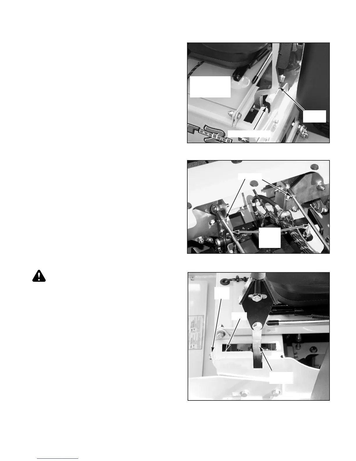
8. After adjusting for neutral it may be necessary to re-adjust the
steering dampener and/or the control lever stop. Fig. 11-23 or Fig.
11-24
11-15
302620 8/06
Figure 11-19
Park brake slot
Control lever
in the neutral
position
Control
lever
Figure 11-20
Pump
linkage
rod
Jam nut
Figure 11-21
Control
lever
Stop
Jam
nut
 Loading...