5. Deck clutch switch (Fig. 3-2) — this switch engages
the deck. Pull the switch up to engage and push switch
down to disengage the clutch.
IMPORTANT: Never engage clutch with engine
running at high rpm or when the deck is under load.
Clutch, belts or deck could be damaged.
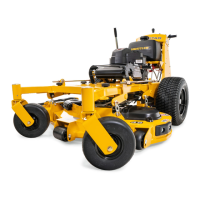
6. Deck lift pedal (Fig. 3-5) — the deck lift pedal is used
to raise or lower the deck. Push on the pedal to raise
the deck and then place the deck height locking pin
into the desired cutting height hole.
Push the deck lift pedal to raise the deck when going
over obstructions.
Instrumentation
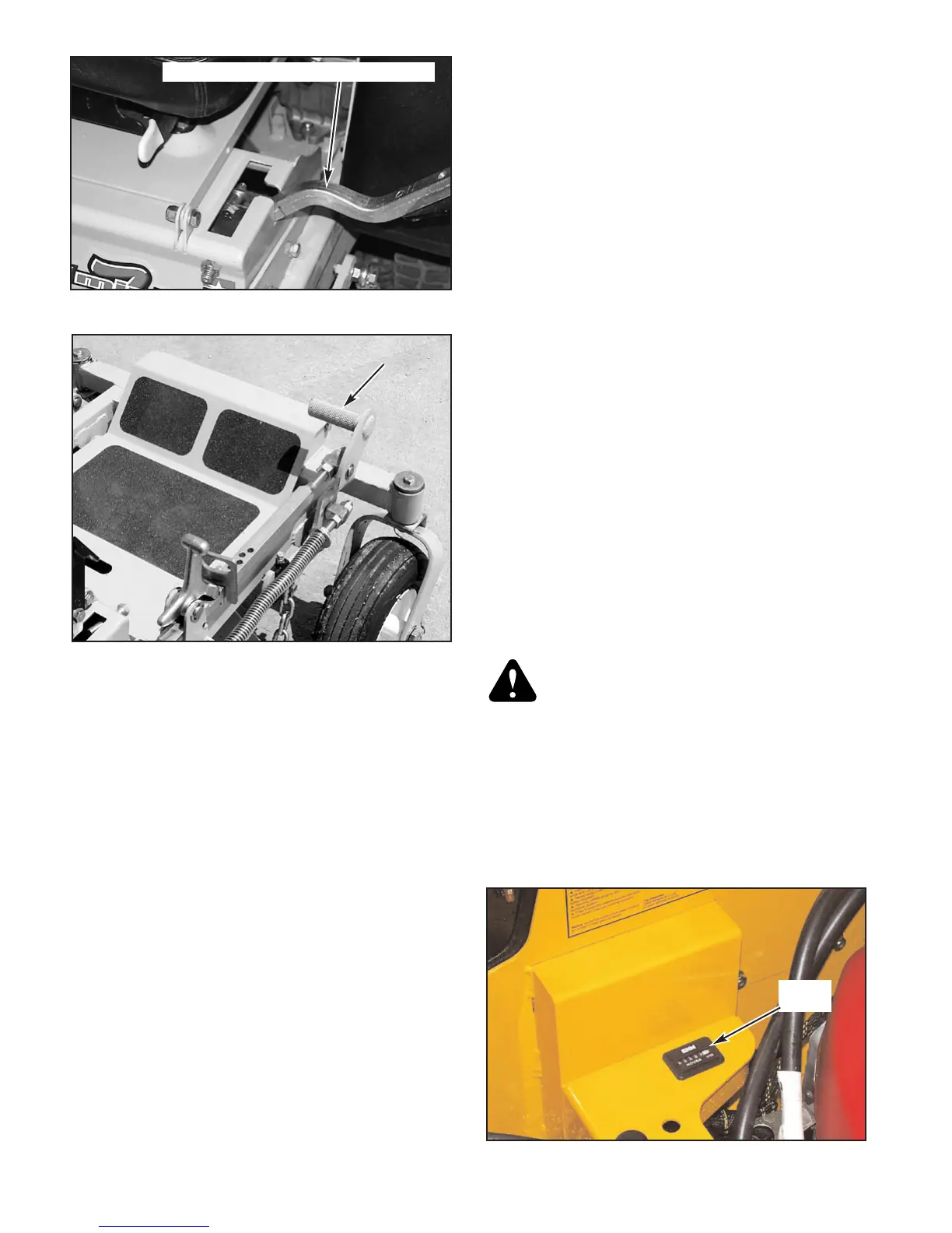
7. Electronic hour meter (Fig. 3-6) — registers 1/10
hour increments up to 9,999.9 total hours. Connected
to the ignition switch, the meter records the
accumulative time while the ignition key is switched to
the RUN position and the operator is on the seat.
8. Oil pressure light (Fig. 3-2) — this light comes on
when the ignition switch is placed in the RUN position
and stays lit until the engine is running and a safe oil
pressure is developed. If light comes on during
operation, shut engine off immediately and locate and
correct the problem.
Safety interlock system
The tractor is equipped with a safety start interlock
system consisting of the park brake switches, seat switch,
and deck clutch switch.
Check tractor safety start interlock system daily, prior to
operation. This system is an important tractor safety feature.
It should be repaired immediately if it malfunctions. The
machine incorporates a separate seat switch which will stop
the tractor engine when the operator is unseated for any
reason while the tractor is operating. This is a safety feature
designed to prevent runaway or accidental entanglement. To
inspect the system:
1. The operator must be on the seat when testing the seat
switch.
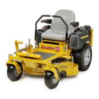
2. Set both control levers in the park brake position.
3. Start the engine and allow it to warm up to operating
temperature.
4. With the deck clutch switch down and the control
levers in the park brake position, slowly raise off of the
seat. The engine should continue to run.
5. With the deck clutch switch up and/or the control
levers in the neutral position, slowly raise off of the
seat. The engine should stop.
6. If the engine fails to stop when the deck clutch switch
is up or one or both of the control levers is up and the
operator is off the seat, check the function of the seat
switch. If the seat switch is not operating properly (is
not opening or closing) and if the cause can not be
determined, replace the seat switch.
If the problem can not be located, contact your Hustler
Dealer.
WARNING: The safety interlock system should
always function per steps 4 and 5. If it does not
function properly, it should be corrected
immediately. Do not operate machine without
properly functioning seat safety switch.
Engine starting
The Mini Z safety start interlock system is also designed
to protect the operator and others from accidental injury due
to unintentional engine starting. The engine starting motor
will not engage until:
302638 Rev 1/05
3-2
Figure 3-5
Deck lift
pedal
Figure 3-6
Hour
meter
Figure 3-4
Control lever in park brake position
 Loading...