2. Before installing a new element, inspect it by placing a
bright light inside and rotate the element slowly,
looking for any holes or tears in the paper. Also check
gaskets for cuts or tears. Do not attempt to use a
damaged element which will allow abrasive particles
to enter the engine.
3. Reinstall the dust cup. Make sure it seals all the way
around the air cleaner body, then tighten the clamps.
4. Check all fittings and clamps periodically for tightness
and inspect hoses for holes or cracks.
5. Periodically check the intake hose for signs of ingested
dust. Locate and repair the source of ingested dirt.
6. Never operate a machine without an air filter installed.
Air restriction indicator
Any unit with a Kawasaki engine will have an air
restriction indicator installed in the air cleaner. Fig. 4-13
Replace the element whenever the restriction indicator
shows reaches the change filter red line. Check the indicator
daily and replace element as needed or annually whichever
occurs first.
Reset the indicator by pushing in on the yellow button
after each element change. Fig, 4-13
A restriction indicator takes the guesswork out of air
cleaner servicing and allows you to safely benefit from the
filter’s optimum performance.
General engine maintenance
Detailed instructions and recommendations for break-in
and regular maintenance are specified in the Engine
Owner’s manual. Please refer to this manual for engine
servicing, lubricating oil levels with quality and viscosity
recommendations, bolt torques, etc. The engine warranty is
backed by the manufacturer. Special attention should be
paid to applicable data which will not be duplicated here.
4-12
302638 Rev 1/05
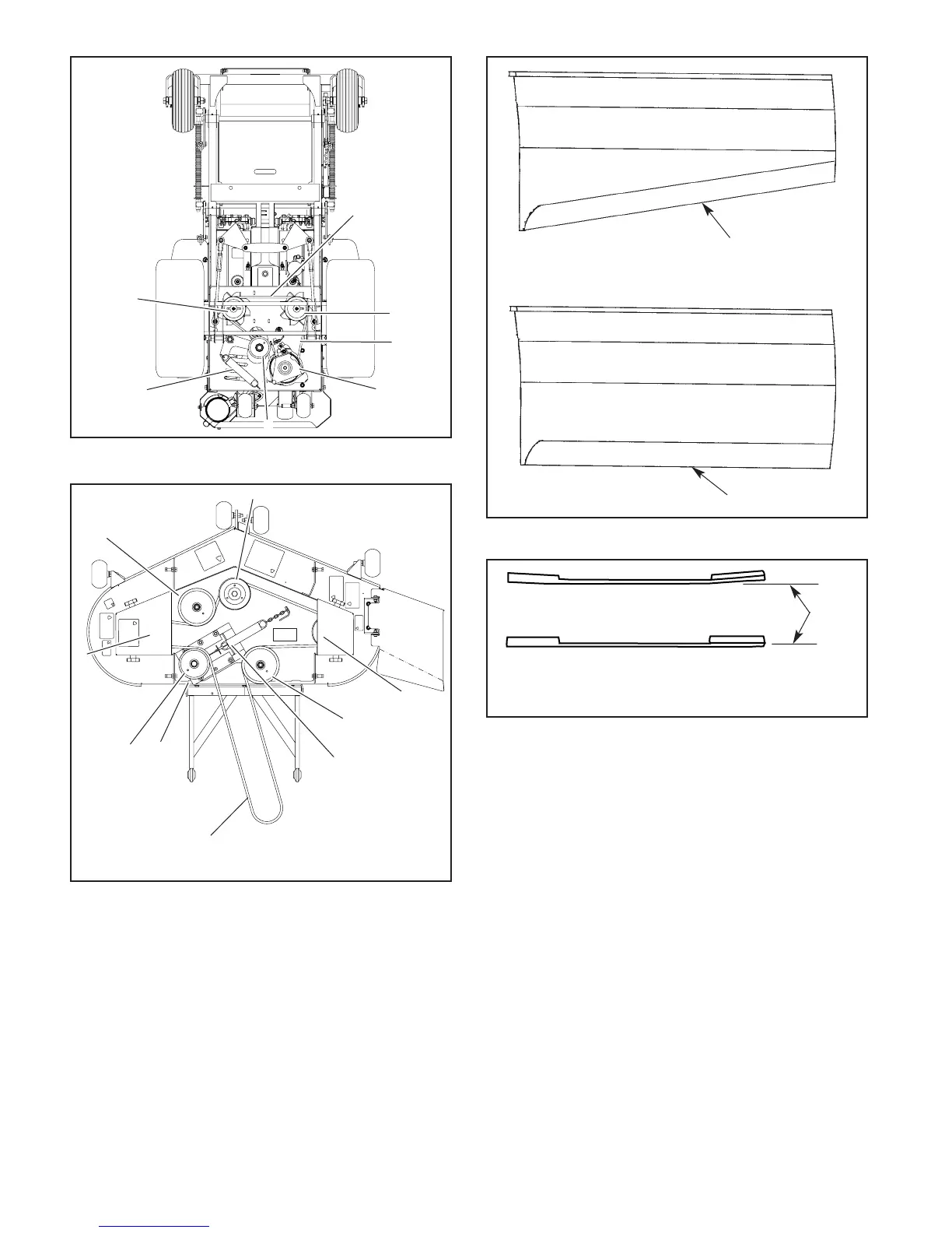
Figure 4-16
Resharpening Pattern
Do not sharpen to original pattern (below).
It is easier to get a straight cutting edge following
the resharpening pattern shown above.
Original Edge
Warped Blade (Replace)
Straight Blade
Comparison of Warped and Straight Blades
Cutting
Plane
Figure 4-17
Figure 4-15
1
Deck Belt Drive Layout
1. Spindle drive belt
2. Deck blade spindle pulley
3. Spindle belt tension idler
4. Spindle belt tension idler spring
(7.75" at operation)
5. Deck belt idler
6. Idler arm
2
2
2
6
4
5
3
5
Figure 4-14
1
2, 6
4
5
1. Pump belt
2. Engine pulley
3. Pump idler pulley
4. Pump idler arm
5. Pump pulley
6. Electric deck clutch
7. Pump idler spring
7
Viewed from
bottom for unit
5
3
 Loading...