Control lever adjustment
The control levers can be adjusted for operator comfort.
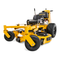
By loosening the cap screws that attaches the upper control
lever to the lower lever (Fig. 5-5), the upper control lever
can be pivoted to fit the operator’s personal preference.
The control levers should be adjusted so that they align
with each other when in the neutral position.
Park brake adjustment
Occasionally check the park brakes and adjustment using
the following method:
1. Position the control levers in the neutral position.
Disengage the deck clutch.
WARNING: Make certain machine is secure
when it is raised and placed on the jack stands.
The jack stands should not allow the machine to
move when the engine is running and the drive
wheels are rotating. Use only certified jack
stands.
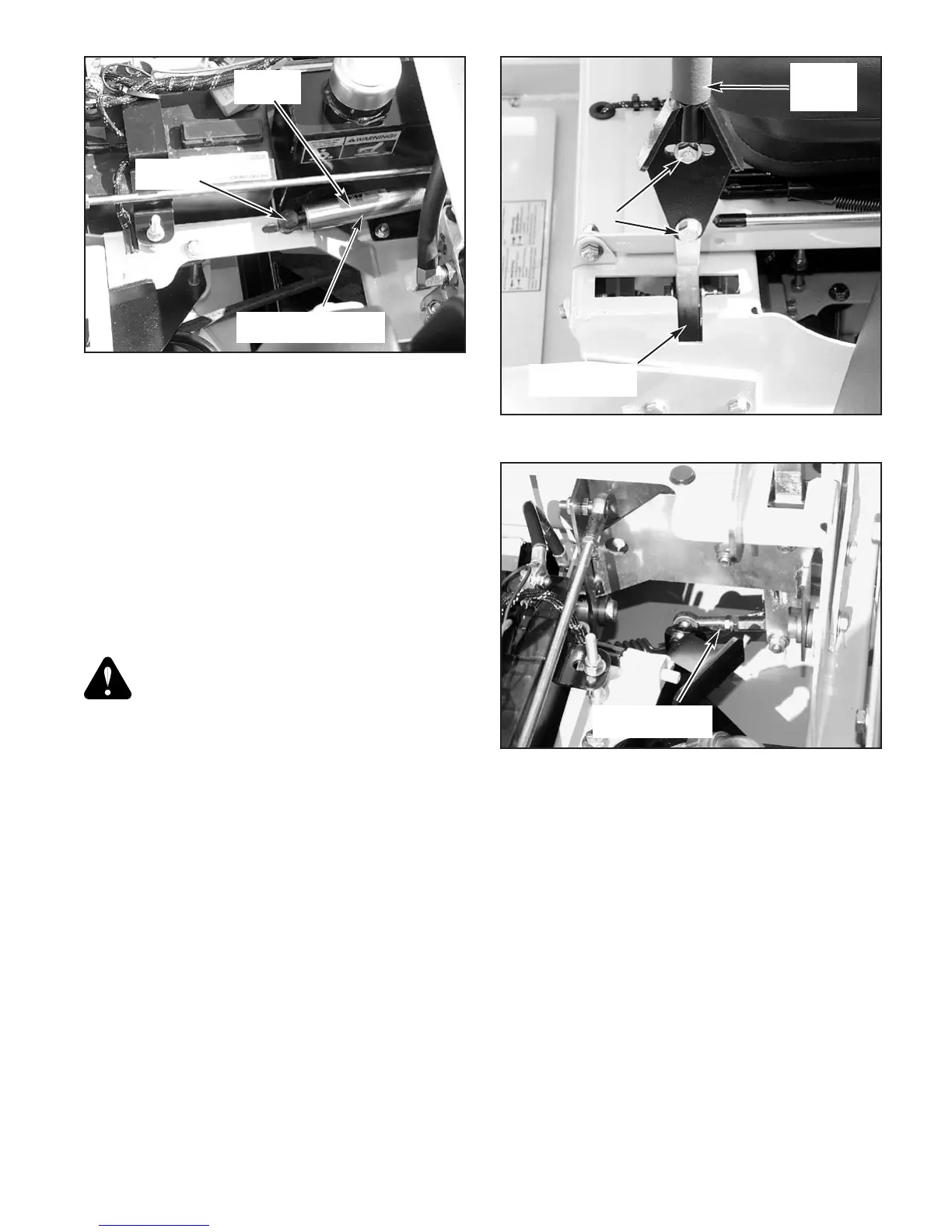
NOTE: The front brake link is not adjustable. Fig. 5-6
2. Raise and block the tractor up so the drive wheels are
off of the floor.
3. Open the hydraulic pump’s bypass valve (Fig. 5-7), on
the side that is being adjusted, by turning bypass valve
counter clockwise one-half to one revolution. The
valve stems on each hydraulic pump are located near
the top and are identified as a hex stud.
4. Rotate the tire. The tire should rotate. Remember
hydraulic oil resistance will prevent the tire from
rotating freely even with the bypass valves open.
There should be no resistance from the brakes at this
point.
5. Move the control lever to where it is just inside (1/8”)
the park brake slot. Fig. 5-8
NOTE: When the control lever is against the outside
edge of the the slot, the brakes should not be engaged.
Fig. 5-9
6. Rotate the tire. If the brake is adjusted properly the
tire will still rotate but friction will start to become
noticeable here. However, if no brake resistance is
noticed, the brake needs adjusted as follows:
7. Loosen the brake linkage jam nuts. Fig. 5-10
8. Rotate the tire and at the same time rotate the
turnbuckle to shorten the length of the brake linkage to
increase the brake pressure. When you feel the brake
begin to engage, stop adjusting the turnbuckle. Re-
tighten the jam nuts on the turnbuckle.
9. Place the control lever in the park brake slot (Fig. 5-
11). The tire should not rotate when the control lever
is in the park brake position.
10. Place the control lever in the neutral position. The tire
should rotate freely.
11. Close the hydraulic pump’s bypass valve.
12. Repeat steps 3 thru 11 for the other side.
13. Remove the jack stands and lower the unit. It is now
ready to operate.
Hydraulic pump belt adjustment
The pump drive belt tension remains constant by means of
a tension idler and spring (Fig. 5-12). There is no tension
adjustment of this belt. NOTE: Replace the belt every 400
302638 Rev 1/05
5-3
Figure 5-5
Cap screw
Upper
control
lever
Lower control
lever
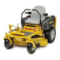
Figure 5-4
Spring
housing
Front ball
stud
Figure 5-6
Front brake link
(right side)
Steering dampener
with spring
 Loading...