REV A 4-4 127180
5. Move the steering control lever on the slower speed
side forward until it makes contact with the steering
control lever stop. Turn the speed adjusting screw
down until it makes contact with the steering handle
stop (finger tight). Tighten lock nut. Figure 4-8
6. Move the steering control lever on the faster speed
side forward until it makes contact with the steering
control lever stop. Turn the speed adjusting screw
down until it makes contact with the steering handle
stop (finger tight). Using a wrench turn the adjusting
screw an additional 1/4 turn. Tighten lock nut.
Figure 4-8
7. Test drive the mower to determine if the wheels are
rotating at the same speed. If not, repeat this
procedure until unit drives straight.
NOTE: Since this is a hydrostatic drive, variables such as
temperature of oil, efficiency of pumps and motors, tire pres-
sure etc. may effect the consistency of the ability to rely on
the stops to drive straight without the operator making minor
steering adjustments with the control arms.
Neutral Switch Adjustment
OIf the engine does not start unless one or both of the
steering control levers is moved, then one or both of the
neutral switches will need to be adjusted.
When the steering control lever is in the neutral position,
the cap screw on the steering control lever should align with
the target circle on the neutral switch. If it does not, then the
neutral switch will need to be adjusted.
1. Place the steering control lever in the neutral position.
2. Loosen the two cap screws that hold the switch. Slide
the switch in the slot to move it. Figure 4-9,
Figure 4-10, & Figure 4-11
3. Loosen the nut on the steering control lever and slide
the cap screw up and down to align the end of it with
the target circle as shown. Tighten nut. Figure 4-1,
Figure 4-10, & Figure 4-11
NOTE: The gap between the end of the cap screw and
the target circle surface should be between .120" and
.150”. The end of the cap screw and the target surface
should not touch.
4. After the cap screw and target circle are aligned
tighten all the hardware.
5. Repeat the procedure, if necessary, for the opposite
switch.
NOTE: If the neutral switch is replaced use the .20" spacer
that is supplied with the switch.
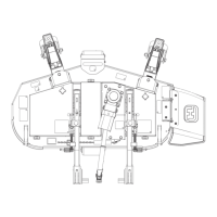
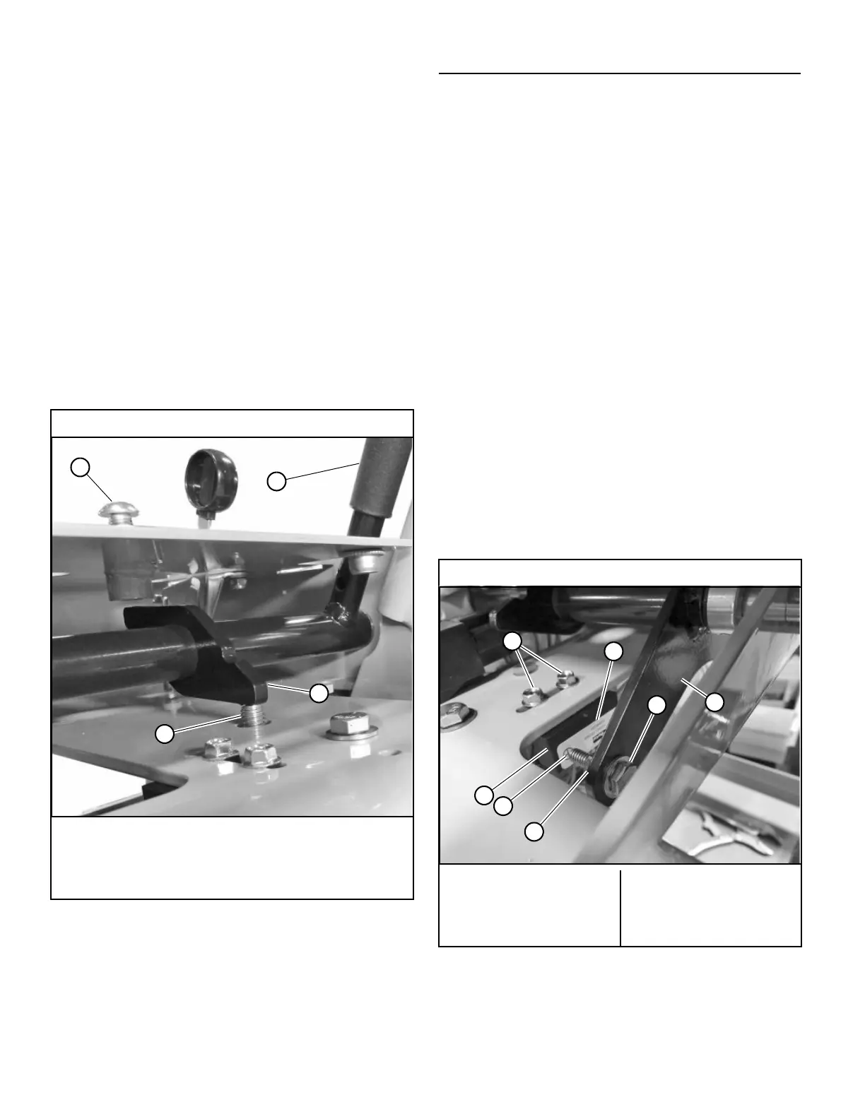
48"/52"/60" Mowers
A. Steering control lever stop screw
B. Steering control lever
C. Speed adjusting screw
D. Steering handle stop
Figure 4-8
36" Mowers
A. Cap screws
B. Target circle
C. Switch
D. Nut
E. Cap screw sensor
F. .20" Spacer
G. Steering control lever
Figure 4-9
 Loading...