REV F 3-4 604345
Control Panel
A. Deck clutch switch (Figure 3-1) — this switch engages
the deck. Pull the switch up to engage and push switch
down to disengage the clutch.
IMPORTANT: For additional clutch information refer
to the Mower deck operation section of this manual.
B. Ignition switch (Figure 3-1) — a three position switch:
“OFF”, “RUN”, and “START”. With key inserted, rotate
it clockwise to “START” position; release key when
engine starts, and switch will automatically return to the
RUN position.
C. Oil pressure light (Figure 3-1) — this light comes on
when the ignition switch is placed in the RUN position
and stays lit until the engine is running and a safe oil
pressure is developed. If light comes on during operation,
shut engine off immediately and locate and correct the
problem.
D. Throttle control (Figure 3-1) — a cable is linked to the
engine throttle for controlling engine speed. Move lever
forward to increase engine rpm, move lever rearward to
decrease engine rpm.
E. Choke control (Figure 3-1) — a cable is linked to
manually operate the engine choke. When the lever is in
the down position, the choke is in the off (run) position.
When the knob is pulled up, the choke is in the on (start)
position. Do not operate the machine in the on (start)
position.
F. Electronic hour meter (Figure 3-1) — registers 1/10
hour increments up to 9,999.9 total hours. Connected to
the ignition switch, the meter records the accumulative
time while the ignition key is switched to the RUN
position.
G. 20 amp fuse (Figure 3-1) — Controller - 20 amp, blade-
type.
H. 15 amp fuse (Figure 3-1) — Ignition & Safety systems -
15 amp, blade-type.
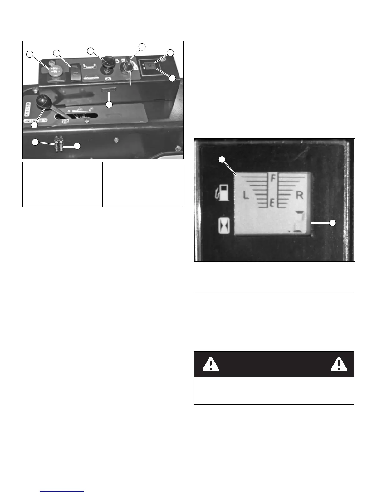
I. Fuel tank gauge (Figure 3-1 & Figure 3-2) — this
gauge shows the fuel level for each fuel tank. The right
gauge indicates the fuel in the right tank and the left
gauge indicates the fuel level in the left fuel tank.
J. Side deck lift switch (Figure 3-1) — this switch raises
and lowers the side decks. Push down on the top of the
switch to raise the side decks. Push down on the bottom
of the switch to lower the side decks.
Controls
K. Steering control levers (Figure 3-3 & Figure 3-4) —
these levers control the mower’s speed, direction,
stopping, and park brake. These levers are used to steer,
accelerate, decelerate and change direction. When the
steering control levers are in the park brake position the
mower will not move when the engine is on and drive
pumps are operating.
L. Center deck lift switch (Figure 3-5) — This switch
raises and lowers the center deck. Step on it to raise the
center deck. The center deck will lower automatically
A. Deck clutch switch
B. Ignition switch
C. Oil pressure light
D. Throttle
E. Choke
F. Hour meter
G. 20 amp fuse
H. 15 amp fuse
I. Fuel tank gauge
J. Side deck lift switch
Figure 3-1
Figure 3-2
The parking brake may not hold the mower if parked on a
slope. Block or chock the machine when parked on a
slope.

 Loading...