604345 3-13 REV F
the chart) the range of cut is 3.0” to 5.5” (76.2mm to
139.7mm).
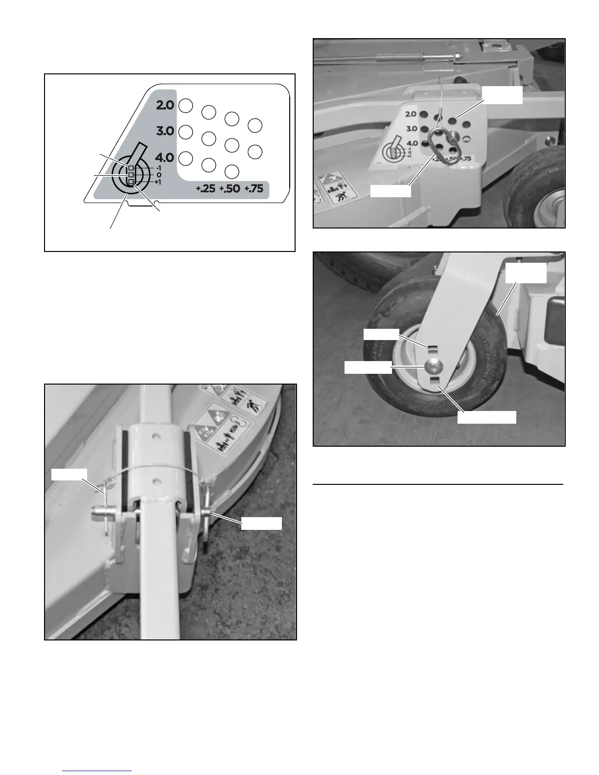
7. On the side decks remove the hair pin from the clevis pin
and remove the pin from the height adjusting hole. Slide
the side wheel arm assembly until a slot aligns with the
desired hole. Slide the pin through the hole and insert the
hair pin. Figure 3-15 & Figure 3-16
8. Unbolt the side deck wheel and move it to the correct
hole. Retighten the nut. Figure 3-17
9. Repeat steps 7 and 8 for the other three side deck
adjusting locations.
Anti-scalp Wheels
Anti-scalp wheels are standard on this mower. These anti-
scalp wheels are designed to minimize scalping when mowing
on rough uneven terrain. Figure 3-18
Anti-scalp wheels can be installed in two positions. With the
wheel installed in the bottom hole, the wheel is located 2”
(50.8mm) below the mower blades. This setting is preferred
when mowing at cutting heights of 2-1/2” (63.5mm) or higher.
When the wheel is mounted in the top hole, it is located 1”
(25.4mm) below the mower blades. This is the acceptable
setting for mowing at cutting heights of 1” (25.4mm) or higher.
Figure 3-14
Figure 3-15
604285
604285
604285
Top hole
Side deck
wheel
Middle hole
Bottom hole
Figure 3-16
Figure 3-17
Adjusting
holes
Clevis pin
Top hole
Side deck
wheel
Middle hole
Bottom hole

 Loading...