5
Overshoot
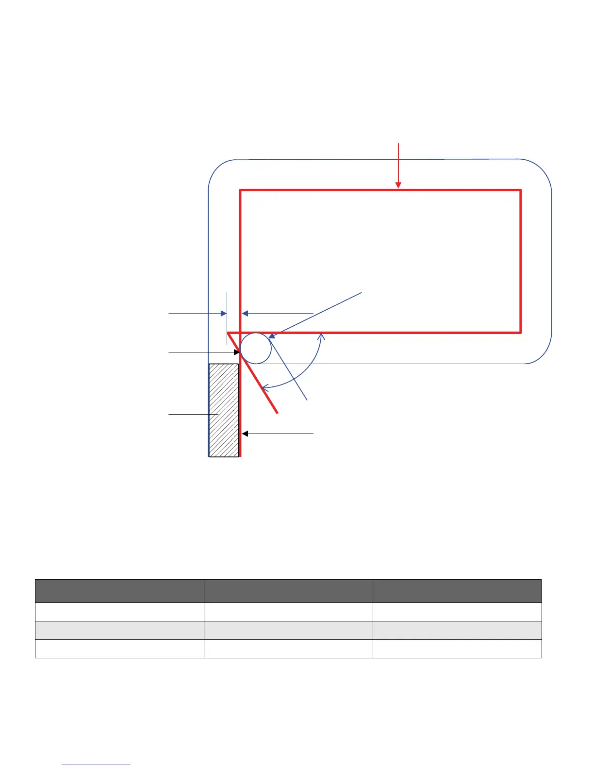
In order for the leading kerf edge to enter the lead-in edge
(with kerf compensation active), the programmed path must
overshoot by some distance (see Figure 6).
Figure 6 – Overshoot definition
This overshoot distance can be calculated using the
following equation:
Overshoot = K
where K is kerf, α is angle, and Correction is an additional
factor necessary to ensure adequate penetration of the arc
into the lead-in section. The Correction factor values for
5–6.25 inches (125–160 mm) are shown in Table 1.
As an example, if α = 60° for a thickness of 6 inches, the
overshoot value is:
K(0.866-0.5+0.25) = 0.68(0.616) = 0.419 inches
Lead-in
Leading kerf edge
Overshoot distance
Kerf width (K)
Lead-in edge
α
Programmed path
1
2
α
2
---
tan
------------------------ -
1
2
---
– Correction+
Table 1 – Correction factors.
Thickness Kerf Correction Factor
5 inches (125 mm) 0.530 inches (13.43 mm) 0.30
6 inches (150 mm) 0.680 inches (17.27 mm) 0.25
6.25 inches (160 mm) 0.700 inches (17.78 mm) 0.25

 Loading...