230V CE INSTALLATION
2-10
230V CE Installation Manual
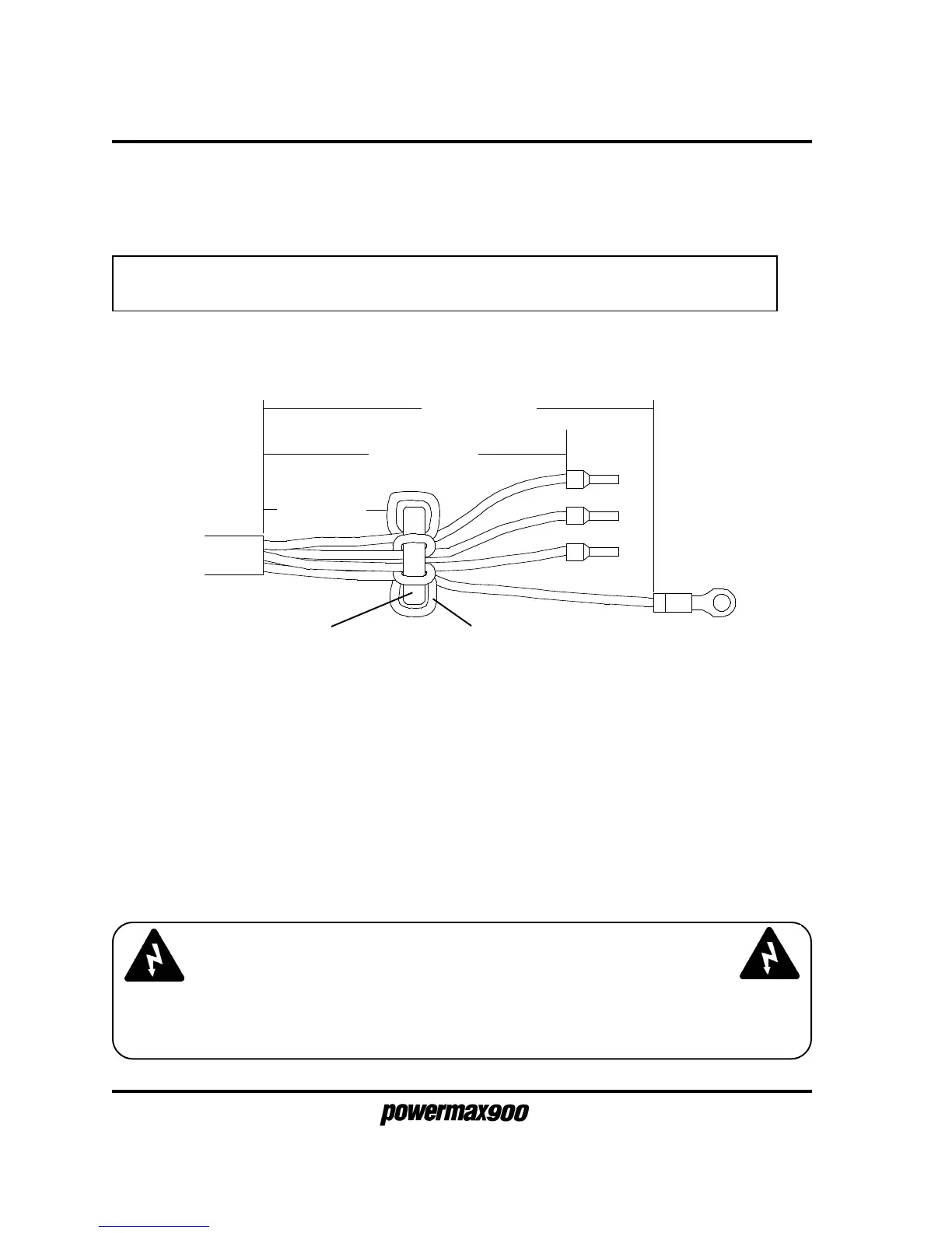
Caution: The toroid must be installed as shown to maintain European EMC compliance.
1. Prepare the power cord wires as shown in Figure 2-9. Note that all 4 wires must loop
through the toroid.
HOOKING UP THE THREE-PHASE TRANSFORMER SECONDARY
POWER CORD FROM 230V TRANSFORMER CASE ASSEMBLY TO
POWERMAX900 CE POWER UNIT
WARNING
BE CERTAIN THAT WIRES ARE CONNECTED AS SHOWN IN FIGURE 2-10. AS A
PRECAUTION, CHECK CONTINUITY FROM POWER SUPPLY ENCLOSURE TO INCOMING
GROUND WIRE BEFORE CONNECTING TO POWER.
Figure 2-9 Power Cord Preparation
2. Connect the power cord wires and the ground wire as shown in Figure 2-10. Be certain
that all wires are fastened securely! Pull on wires after fastening to verify that they
will not come loose.
3. Connect the rear panel to the Powermax900 power supply and secure with screws.
4. Tighten the strain relief around the power cord. Be certain that the strain relief grips the
outer insulation of the power cord and not the individual wires.
5. Replace the power supply cover. See completed assembly in Figure 2-1.
Loop all 4 wires 1 turn
through toroid
Toroid
0.5" (13 mm)
3.75" (95 mm)
4.75" (120 mm)
 Loading...


