EasyManuals Logo
Home>Hypertherm>Welding System>powermax1000

Hypertherm powermax1000 User Manual

Hypertherm powermax1000
69 pages
To Next Page IconTo Next Page
To Previous Page IconTo Previous Page
Page #41 background imageLoading...
Page #41 background image
SETUP
0
3-14 powermax1000 Operator Manual
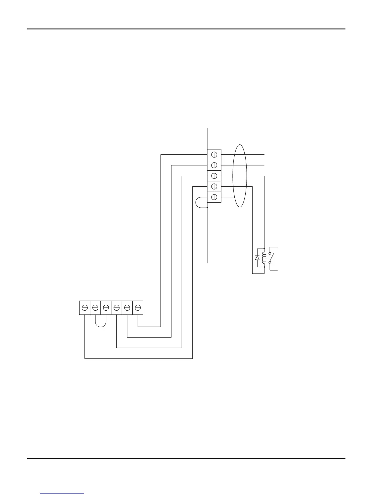
Changing XFER (start machine motion) from dry contact closure to voltage signal
24 VDC (chassis ground reference) at 100ma max is available at J19 on Power PCB to drive a
Isolated/Floating device such as a 24 VDC relay coil (240 ohms or greater) or a Typical Industrial Input
Isolation Module (which has an opto-coupler built-in). Shown below are typical connections for a high side
drive arrangement.
Driving a Relay Coil
Notes:
1) 24 VDC Relay
Recoil >240 ohms
2) Must use suppression
diode (1A, 100V)
such as IN4002
through IN4004 type
across coil.
Move Black wire and add
Jumper as shown
GND
24VDC
BLK
YEL
RED
WHT
J19 XFER
START
SIGNAL
BLK
SHIELD
START
4
3
14
12
13

Table of Contents

Other manuals for Hypertherm powermax1000

Questions and Answers:

Question and Answer IconNeed help?

Do you have a question about the Hypertherm powermax1000 and is the answer not in the manual?

Hypertherm powermax1000 Specifications

General IconGeneral
BrandHypertherm
Modelpowermax1000
CategoryWelding System
LanguageEnglish

Related product manuals