• PV modules of the connected strings must be of: the same type, identical
alignment and identical tilt.
• The thresholds for the input voltage and the input current of the inverter must be
adhered to (see Section 10.1 "Technical DC input data").
• On the coldest day based on statistical records, the open-circuit voltage of the PV
array must never exceed the maximum input voltage of the inverter.
• The connection cables of the PV modules must be equipped with the connectors
included in the scope of delivery.
• The positive connection cables of the PV modules must be equipped with the
positive DC connectors. The negative connection cables of the PV modules must be
equipped with the negative DC connectors.
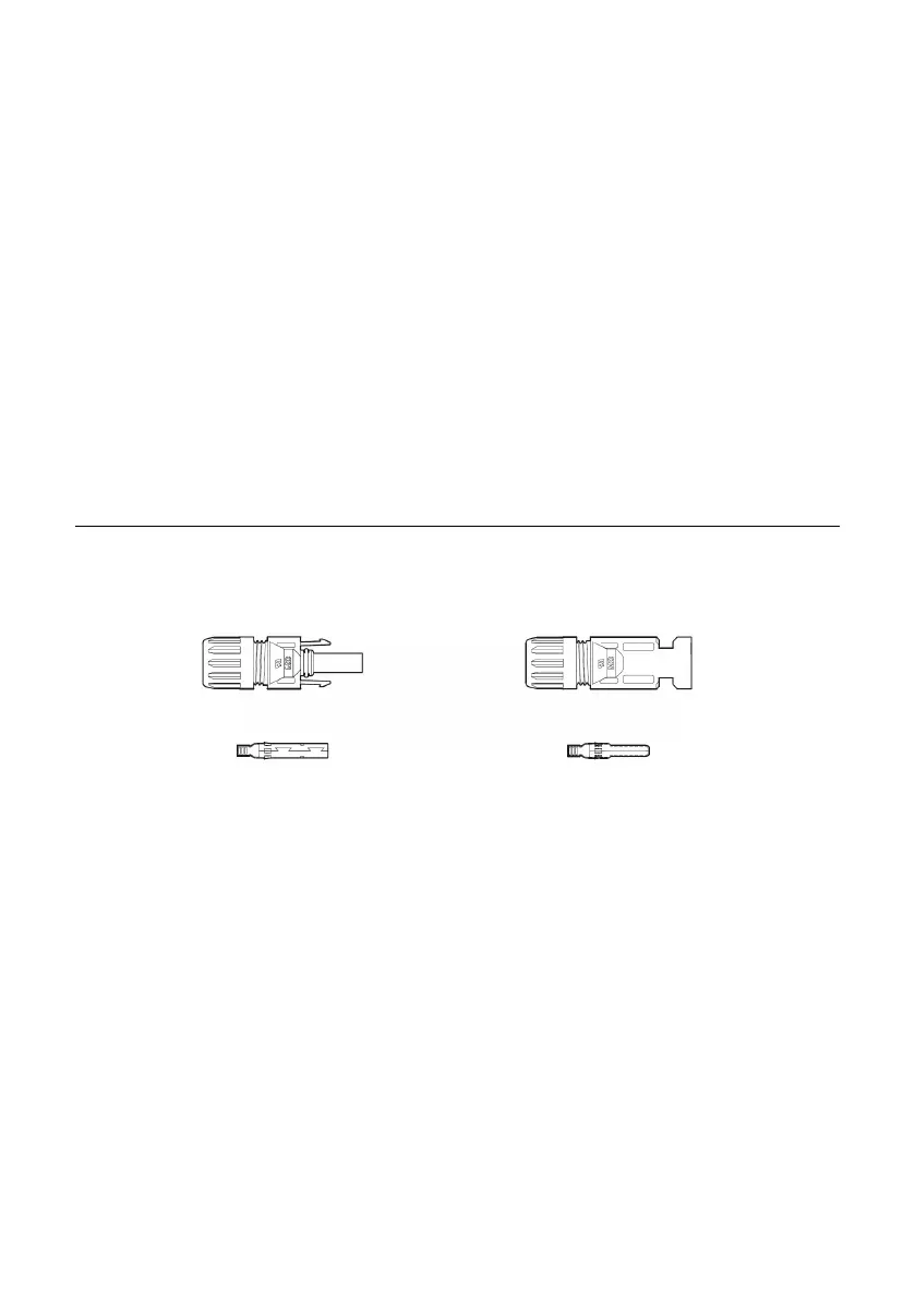
5.4.2 Assembling the DC connectors
Assemble the DC connectors as described below. Be sure to observe the correct
polarity.
Cable requirements:
The cable must be of type PV1-F, UL-ZKLA or USE2 and comply with the following
properties:
External diameter: 5 mm to 8 mm
Conductor cross-section: 2.5 mm² to 6 mm²
Number of conductors: at least 7
Nominal voltage: at least 600V
Proceed as follows to assemble each DC connector.
1. Switch off the DC-switch and secure against being inadvertently switched back
on. Eliminate any existing ground faults or short circuits in the strings.
2. Strip the cable as follows:
 Loading...