Temp. °F/°C
Resist.
Ω – Ohm
Temp. °F/°C
Resist.
Ω – Ohm
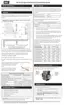
75 / 24 10,501 175 / 79 1,281
80 / 27 9,299 180 / 82 1,172
85 / 29 8,250 185 / 85 1,073
90 / 35 7,334 190 / 88 983
95 / 35 6,532 195 / 91 903
Table 12 Temperature sensor resistance values - 10K ohms
8.2.2 Fan
Operating power is provided by means of a separate 120 VAC connector (white/black/green). Control
of the fan is provided via a four-lead connector. This connector feeds a PWM control signal (black wire)
from the controller and provides a tachometer signal (white wire) back from the fan. Unplugging the
control connector will cause the fan to go to high speed and trigger a “Blocked Vent Error” within 6
seconds if the boiler is operating.
8.2.3 Air pressure sensor
The air pressure sensor monitors air flow in the venting system. If airflow through the combustion air
intake or the exhaust vent becomes too restricted for safe operation, the boiler will stop firing, and
display a "Fan Pressure Error". Also, to prevent avoidable Fan Pressure Errors, the system decreases
the fan speed if the reading from the sensor nears the error threshold.
8.2.4 Water pressure sensor
The water pressure sensor ensures that there is adequate pressure in the heating system for safe
operation. The pressure is displayed in PSI as the default. If the system pressure should drop below
8PSI the firing rate of the boiler is reduced. If the pressure drops to 4PSI or lower, the boiler will not fire.
Check the operation of the sensor by isolating the boiler from its system piping, and close the system
fill valve, and then crack the pressure relief valve. The pressure displayed should reflect declining
pressure. If it remains “fixed”, drain the boiler and replace the sensor, or dislodge any blocking debris
from the sensor inlet channel and reinsert.
 Loading...