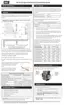
Figure 53 Location of screws securing mixing device to fan
8. Use a 7mm wrench to remove the four screws at the base of the fan (attaching the fan to the
heat exchanger lid). It may help to unplug the ignitor for easier access.
9. Lift off the fan, and replace with the new fan. Ensure that the fan O-ring stays seated in the
fan groove during reassembly.
10.
Reinstall the components in reverse order. Upon reassembly, ensure that all O-rings and
gaskets are correctly positioned.
Warning
Ensure that the fan O-ring is seated in the groove of the fan when reassembling.
7.2.2 Replacing the gas valve in the EX 400 and EX 500 models
1. Turn off the electric power and gas supply to the boiler.
2. Ensure that the boiler cools down to the surrounding temperature.
3.
Remove the front cover, and then remove the four Torx 20 head screws on the top panel of the
boiler.
A ladder or step may be required to have a clear vertical view of the work area. Do not attempt
to reach from the front without a clear view, as damage to the connectors or screws may
occur.
4.
Disconnect the gas valve wiring, and pull out the connectors by gripping the plastic tip, rather
than the wire, to avoid breaking the connector (see j and in Figure 54 ). Note the position of
the colored wires; do not cross the colored wires upon reconnection (e.g., blue on top).
7.2.2 Replacing the gas valve in the EX 400 and EX 500 models
 Loading...