2-1
BOILER SYSTEMS AND OPERATION
VFC 15-150 - VFC 45-225 MODULATING GAS BOILERS
BOILER SYSTEMS AND OPERATION
2.0
2.1 GENERAL
VFC modulating series boilers are designed to service three separate, directly
piped heating loads using different pre-selected water temperatures and heat
regulation routines. External controls can extend applications.
Thecontrolisoutttedtoprovideforoutdoorreset,setpointregulationandDHW.
ThedesignobjectiveisDHWplusradiantoorandbaseboardspaceheating,
each operable at a unique temperature.
While the three load “channels” are shipped pre-programmed with default values,
they can each be programmed with DHW, set-point control or outdoor reset
parameters (see Section 2.7 Set Up and Load Denition). The strategy is to
deliver high temperature water, as required by most indirect DHW tanks on the
market,andbynnedtubebaseboards,butdefaulttothelowestpossibleboiler
supplytemperaturetomaximizeefciency.TheVFCmodulatingseriesboilers
can handle supply temperatures within the range 34°F to 185°F.
CONTROL
The control unit provides overall management of boiler operations, including:
1. Power-up / set-up / boiler state machine (standby / heat call management
etc).
2. Burner, pumps (primary + external) and/or zone valve management.
3. Temperature and throttle operation.
4. Maintenance of a service log with diagnostics.
5. 2 way communications.
Operating and historical data may be accessed at any time, using the Log and
AdvancedSettingselds,availableusingthepermanentlylitLCDscreen.See
below. Data includes the following:
• Ignition counter
• Time records, including burn time by load and the throttle duty cycle
• Error log
USER INTERFACE
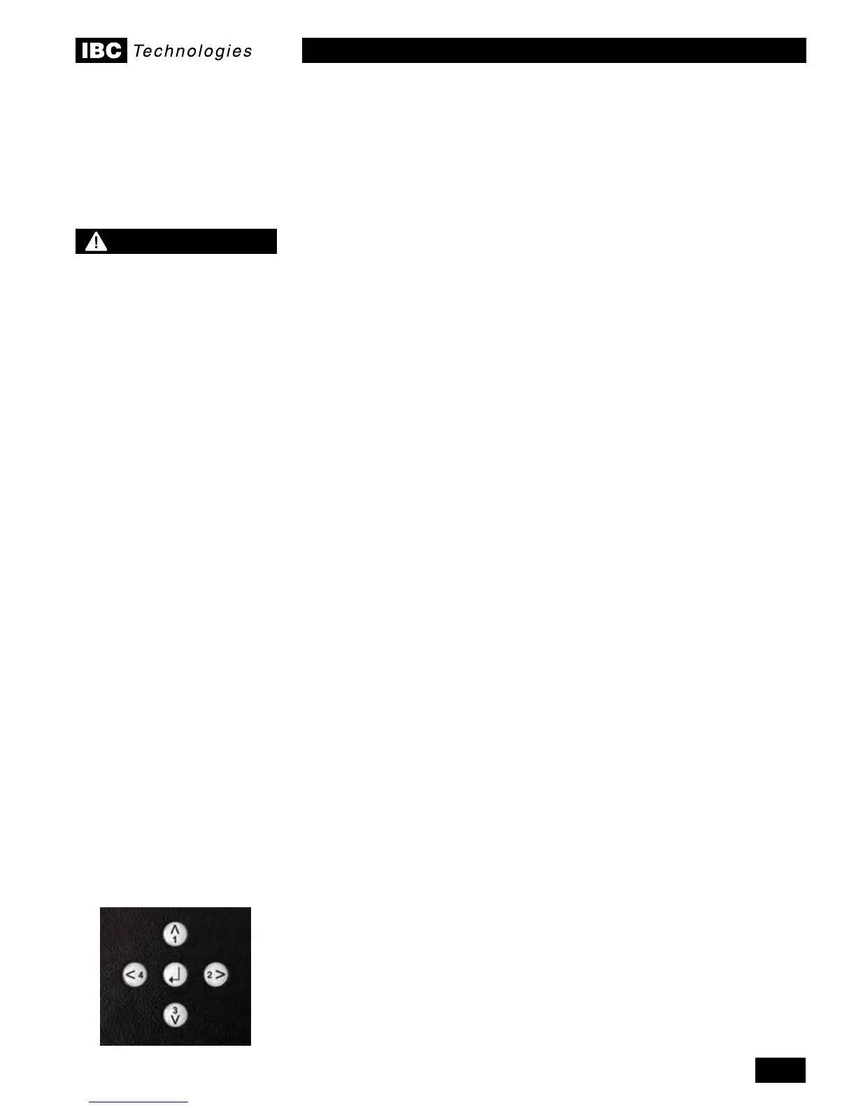
2.3.1 Keypad Functions
Avebuttonkeypadisprovidedforintuitivenavigationaroundthescreen.The
four outer keys are used to move the cursor up or down, and side to side. The
centrebuttonisusedtomakeselectionsandconrminputs.Thelefthandkey
is also used to back-step to the previous screen; multiple key stokes are used to
withdraw back to the operating status screen.
2.2
WARNING
If the boiler can become
exposed to uid temperatures
below 34°F (1°C), a method of
protection to prevent freezing
of condensate should be
employed. Contact the factory
for further information.
2.3
 Loading...


