INSTALLATION AND OPERATION INSTRUCTIONS
5-4
VFC 15-150 - VFC 45-225 MODULATING GAS BOILERS
Next,conrmthatthecircuitisproperlypowered.Thesupplyvoltagetothe
sensor should be 13.8 VDC; to check, the simplest technique is to measure the
circuit on the face of the controller circuit board (vs. an attempt to splice into the
harness / connectors). See above for a presentation of the measurement points.
Finally, to measure the sensor output, connect a DC volt meter between points
“J501-33” (located on the footprint of the 34 pin connector – immediately below
the right leg of the LCD display - second pin from bottom right) and GND (see
above). With the fan off, the measure should read 0.5VDC. With a Fan Pressure
of approx. 300, the meter will read 1.5v (approx.). Note:- this component is a
sensor, not a switch; do not over-pressurize by blowing into the air reference
lines. Maximum pressure capacity is 40” w.c. @ 20 C but only 10” w.c. @ 5C.
5.2.4 Water Pressure Sensors
Go to the Advanced Diagnostics screen, and check the top 2 display lines —
Inlet Pressure and Outlet Pressure. With the pumps at rest and system pressure
of 12.5 psi, the Inlet Pressure and Outlet Pressure sensor values should read
235 +/- 5. Of the two, while at rest, the Inlet normally reads 1 – 2 points higher,
reectingtheextra2'ofwatercolumn.ThethirddisplayedlineDeltaPressurewill
normally indicate a value of approx. 20 with pump in operation. The location of
the boiler pump will determine the movement of valid sensor values; in general,
inlet pressure will increase while the outlet will decrease when the pump starts.
Check operation of both sensors by isolating the boiler from its system piping,
closingthesystemllvalvethencrackingthepressurereliefvalve;bothsignals
shouldreectdecliningpressure.Ifoneorbothremain“xed”,drainboilerand
replace sensor(s), or dislodge any blocking debris from sensor inlet channel
and reinsert. To remove a red-coloured “502” sensor, it is necessary to release
a stainless steel retaining clip at the base of the unit (see Section 6.1 Parts
Diagrams,part#65).Beforerellingsystem,ensurethe502sensorretainerclips
are properly re-installed. The black “505” sensors are threaded and do not use
the retainer clip system.
5.2.5 Hi-Limit Switch (water and vent)
Check resistance between leads. If resistance is very low, temperature should
be acceptable. If resistance is very high, temperature should be out of bounds.
A simple means of checking whether a high limit switch is open is by measuring
the AC voltage across the device. If the reading is 24 VAC the switch is open. If a
0VAC reading is shown, it is closed. NEVER connect an ohm-meter or continuity
checker across a live circuit.
5.2.6 Ignition Module
There are two approved ignition modules - Fenwal (grey) and Capable Controls
(white). Each have a red LED lamp providing the following signals: Fenwal – 1
rapidashon1stenteringPre-purge,3rapidashesuponFailuretoIgniteAfter3
Attempts;theCapableControlsmoduleprovidesasingleashatthestartofeach
PurgeandInterpurgecycle,continuousrapidashesduringthe4secondspark
interval, solid illumination following successful ignition until burner shutdown, and
a slow on/off cycle with a 3-try failure.
Flame current can be monitored on the Fenwal. Connect an electrical test
meter-settoreadMicroamps(symbolμA)tothetwotestpinsatthetoprightof
the ignition module. Recycle the boiler so it enters another trial for ignition and
monitortheamecurrentreading.Whentheburnerignites,asteadyreadingof
Do not blow into sensor ports
Air pressure sensor mounting
Return water pressure sensor
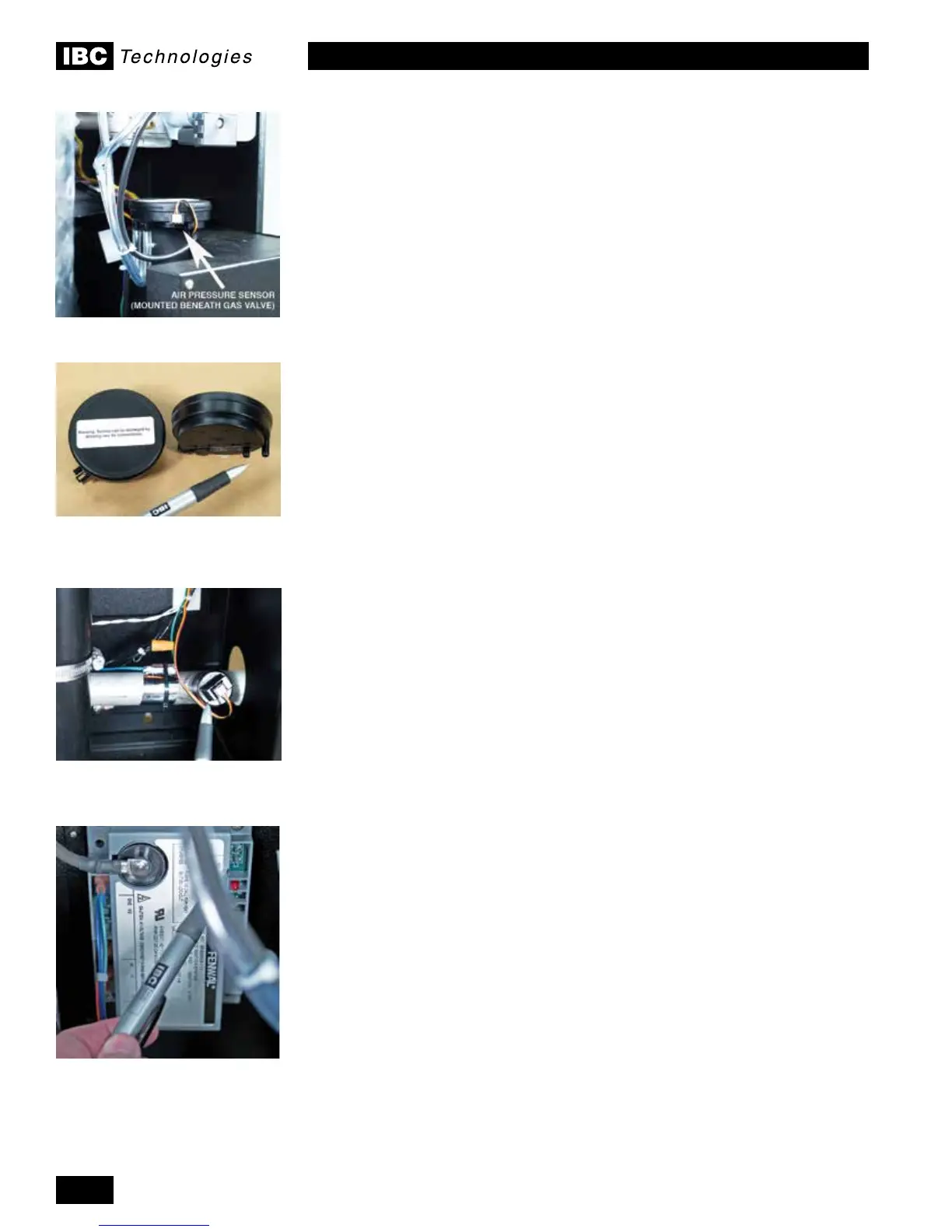
Fenwal ignition module - Microamp
(μA) test points are shown at top
right corner of module (above red
L.E.D.)
 Loading...


