INSTALLATION AND OPERATION INSTRUCTIONS
3-2
VFC 15-150 - VFC 45-225 MODULATING GAS BOILERS
3.2 PRIOR TO START-UP
3.2.1 Pre-Ignition Checks
1. Ensureventingsystemiscompleteandsealtested.Conrmanycommon
venting system at the installation site is isolated and independent of the VFC
boiler, that any holes left from removal of a previous boiler have been sealed,
andthatanyresizingoftheolduehasbeendone.Fillcondensationtrapto
full neck height.
2. Checkwaterpipingsystemisfullyushedandcharged,andthatallairhas
been discharged through loosened bleed caps. Note it is possible to switch
all pumps on/off from the keypad – without a call for heat. This greatly
simpliessystemllingandairbleeding(gotoInstaller Setup, drop down
to Pump Purge and toggle to On. When complete, return to Off, or this will
automatically occur with a call for heat). Use a minimum water pressure of 12
psig.Andconrmpressurereliefvalveisinstalledandsafelydrained.
3. Performanalcheckofelectricalwiring.
4. Using a manometer, check to see that adequate gas pressure is present
at the inlet gas supply test port. Requirements are minimum 3” w.c and
maximum 14” w.c.
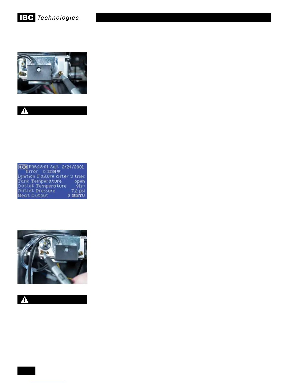
3.2.2 Test Ignition Safety Shutoff
With the boiler in operation, test the ignition system safety shutoff device by
shutting the manual gas valve immediately outside the boiler case. Ensure
boiler has shut off and the appropriate Error information is displayed on the LCD
screen. To restart boiler, reset power.
COMMISSIONING
The VFC modulating boilers are factory calibrated to operate with natural gas (or
propane if so ordered) at sea level. The relevant valve adjustment screws have
been factory sealed using Loctite thread-lock compound, which can be broken
where required. However, no mixture adjustment shall be performed unless
done by a qualied technician using properly functioning combustion
analyzing equipment.
Upon initial set up, the installer can enter the site elevation to compensate
for altitude. Without such intervention, the gas valve will automatically de-rate
the maximum input in accordance with the density altitude, at approximately 2%
per 1,000’ above sea level. The gas valve’s zero governor will ensure that the
gas:air mixture is not affected at altitude.
Toverifytheproperoperationofthegasvalveintheeld,thefollowingprocedure
canbecarriedoutbyaqualiedtechnician(see Figure 31).
1. withasmall(1/8"or3mm)atscrewdriver,openthemanifoldpressure
test port by turning its centre- screw 1 full turn counterclockwise. Attach a
manometer between the manifold pressure test port and the reference line.
2. Allowtheboilertoignite/runagainstalargeload,tomaintainhighre
3. With the boiler at maximum output, use a 2 mm hex key to adjust the zero-
offset (see Figure 31, “A”) as required to achieve 0” wc. This adjustment is
only necessary if this screw has been tampered with.
3.3
Inlet gas supply pressure test port
Manifold pressure test port
DANGER
Making adjustments to
the IBC gas valve without
a properly calibrated gas
combustion analyzer and by
persons who are not trained
and experienced in its use
is forbidden. Failure to use
an analyzer can result in an
immediate hazard.
WARNING
Fill trap with water before boiler
is rst red to prevent exhaust
fumes from entering room.
Never operate the boiler unless
the trap is lled with water.
Failure to comply will result in
severe personal injury or death.
 Loading...


