1-3
INSTALLATION
VFC 15-150 - VFC 45-225 MODULATING GAS BOILERS
contaminants; combustion air should be drawn from a CLEAN source
(e.g. outdoors) and the boiler should be isolated from interior dust
sources. Do not seal boiler case openings directly when ring - allow for
air circulation and ventilation in the immediate area.
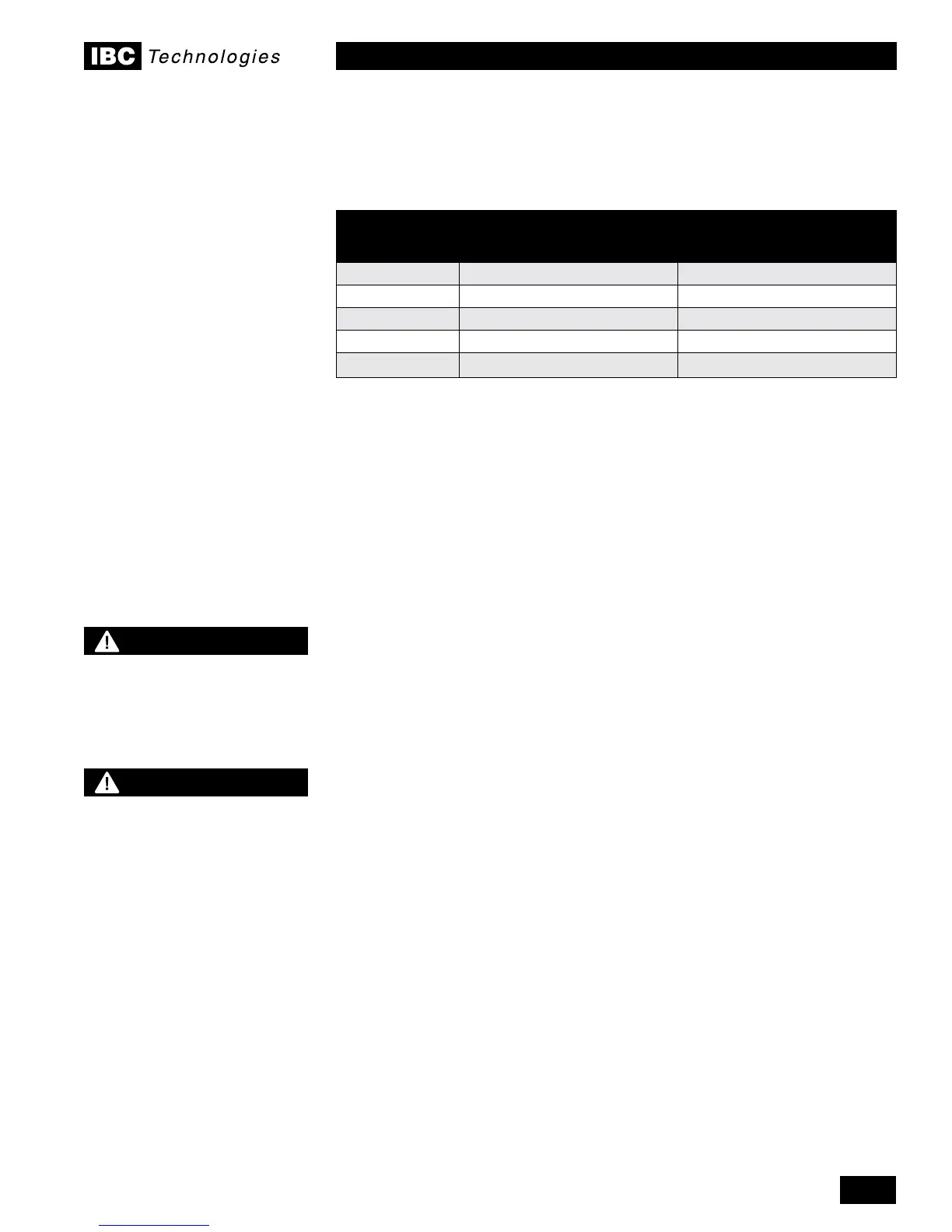
SURFACE
DISTANCE FROM
COMBUSTIBLE
SURFACES
RECOMMENDED
DISTANCE FOR
SERVICE
Front 2" 24"
Rear 0" 0"
Left Side 0" 8" (for vent run)
Right Side 2" 18"
Top 6" 10"
Table 2 - Clearance from boiler cabinet
Distance below the boiler of up to 15" (15-150 model) and up to 24” (45-225
model) is required to provide clearance for the inlet and exhaust venting
together with the required condensation trap. See page 1-15.
EXHAUST VENTING AND AIR INTAKE
It is important to carefully plan the installation to ensure the appropriate
vent materials, travel and termination decisions are incorporated. Specic
attention is warranted to manage the impact of the steam plume normally
experienced at the exhaust terminal of a condensing boiler. Generally,
intake and exhaust pipes should terminate at a rooftop or sterile wall
location, to maximize customer satisfaction. Keep exhaust plumes
well away from all building air intakes including those of neighbouring
properties.
All venting must be installed in accordance with the requirements of the
jurisdiction having authority: in Canada, Part 8, Venting Systems of the B149.1-
10 Code and any other local building codes are to be followed. In the USA
the National Fuel Gas Code, ANSI 223.1, latest edition, prevails. Where there
is a discrepancy between the installation instructions below, and the code
requirements, the more stringent shall apply.
IMPORTANT
When an existing boiler is removed from a common venting system, the common
venting system is likely to be too large for proper venting of the appliances
remaining connected to it.
When resizing any portion of the common venting system, the common venting
system should be resized to approach the minimum size as determined using the
appropriate tables in the National Fuel Gas Code, ANSI Z223.1 - latest edition. In
Canada, use the B149.1-10 Installation Code.
At the time of removal of an existing boiler the following steps shall be followed
with each appliance remaining connected to the common venting system placed
in operation, while the other appliances remaining connected to the common
venting system are not in operation.
1.4
DANGER
Do not common vent the VFC
modulating series boilers
with any other existing or new
appliance.
WARNING
Venting, condensate
drainage, and combustion
air systems for all IBC
boilers must be installed in
compliance with all applicable
codes and the instructions of
their respective Installation
Manuals.
Inspect nished vent and air
piping thoroughly to ensure
all are airtight and comply
with the instructions provided
and with all requirements of
applicable codes.
Failure to comply will result
in severe personal injury or
death.
 Loading...


