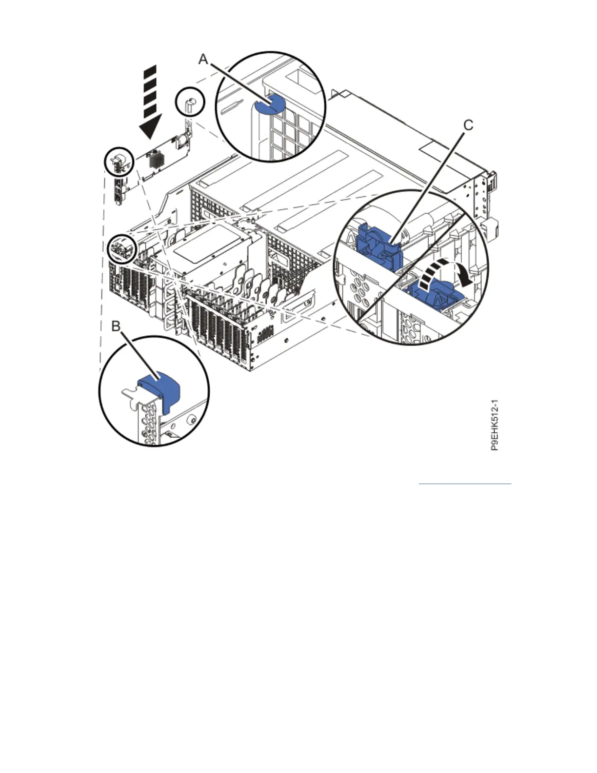
Figure 13. Installing the service processor card into slot P1-C1
4. Plug the front and rear USB cables into the system backplane as shown in Figure 14 on page 17.
• The front USB connector on the system backplane has the USB port symbol with an arrow that
points to the front of the system.
• The rear USB connector on the system backplane has the USB port symbol with an arrow that points
to the rear of the system.
16
Power Systems: Power Systems: Service processor card
 Loading...