v If the thermal-grease protective cover (for example, a plastic cap or tape liner) is
removed from the heat sink, do not touch the thermal grease on the bottom of
the heat sink or set down the heat sink. For details, see the information about
thermal grease in the Problem and Determination Service Guide.
Note: Removing the heat sink from the microprocessor destroys the even
distribution of the thermal grease and requires replacing the thermal grease.
v To order an additional optional microprocessor, contact your IBM marketing
representative or authorized reseller.
To install an additional microprocessor and heat sink, complete the following steps:
Procedure
1. Read the safety information that begins on “Safety” on page v and “Installation
guidelines” on page 43.
2. Turn off the server and peripheral devices and disconnect the power cords and
all external cables.
3. Remove the cover (see “Removing the cover” on page 51).
4. Locate microprocessor socket 2 on the system board.
5. Remove the microprocessor 2 air baffle (see “Removing the microprocessor 2
air baffle” on page 53).
6. Install the microprocessor:
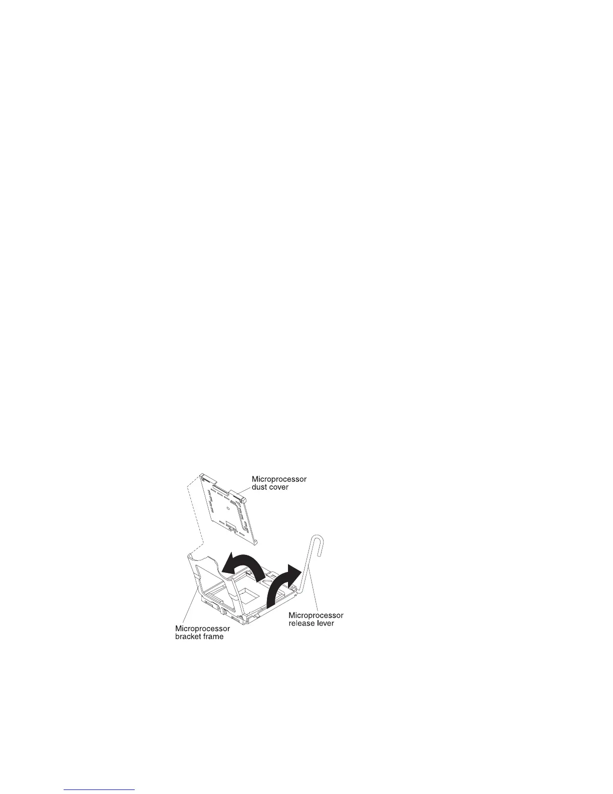
a. Press down and out on the release lever on microprocessor socket 2 and lift
up the microprocessor release lever until it stops in the fully open position.
b. Lift the hinged microprocessor bracket frame into an open position and
remove the microprocessor dust cover, tape, or label from the surface of the
microprocessor socket, if one is present. Store the dust cover in a safe place.
Attention: When you handle static-sensitive devices, take precautions to
avoid damage from static electricity. For details about handling these
devices, see “Handling static-sensitive devices” on page 46.
c. Locate the microprocessor installation tool that comes with the new
microprocessor.
Note: The microprocessor installation tool assembly comes with the
microprocessor and microprocessor cover attached to the tool. The
Figure 78. Dust cover removal
Chapter 2. Installing optional devices 101
 Loading...


