i
IMPORTANT
READ ALL INSTRUCTIONS carefully and com-
pletely before using the AT-130 and AT-130E.
SAVE THIS INSTRUCTION MANUAL. This
instruction manual contains important safety and in-
stallation instructions.
PRECAUTIONS
R DANGER HIGH VOLTAGE! NEVER touch
the antenna terminal, ground terminal, antenna or
counterpoise while transmitting. Place the AT-130
or AT-130E, antenna and counterpoise in positions
where no one touches them.
R WARNING! NEVER transmit during internal
adjustment. This may cause an electric shock.
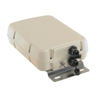
NEVER use without a ground connection.
USE the ground terminal for ground connection. The
mounting plate is not connected internally.
Ground terminal
Mounting plate
DO NOT operate your HF marine transceiver without
running the boat’s engine.
DO NOT use the AT-130 or AT-130E in areas where
the temperature is below –30°C (–22˚F) or above
+60°C (+140˚F).
EXPLICIT DEFINITIONS
The explicit definitions in this instruction manual.
WORD DEFINITION
RDANGER!
Personal death, serious injury or an
explosion may occur.
RWARNING!
Personal injury, fire hazard or elec-
tric shock may occur.
CAUTION Equipment damage may occur.
NOTE
If disregarded, inconvenience only.
No risk of personal injury, fire or elec-
tric shock.
FOREWORD
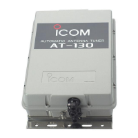
Thank you for purchasing the AT-130 or AT-130E HF
AUTOMATIC ANTENNA TUNER.
The AT-130 and AT-130E are designed, primarily for
use with Icom HF transceivers. To meet with European
regulations, the AT-130E includes an extra emergency
tuner circuit for 2182 kHz operation.
Refer to your HF transceiver instruction manual for op-
eration. If you have any questions, contact your nearest
authorized Icom Dealer or Service Center.
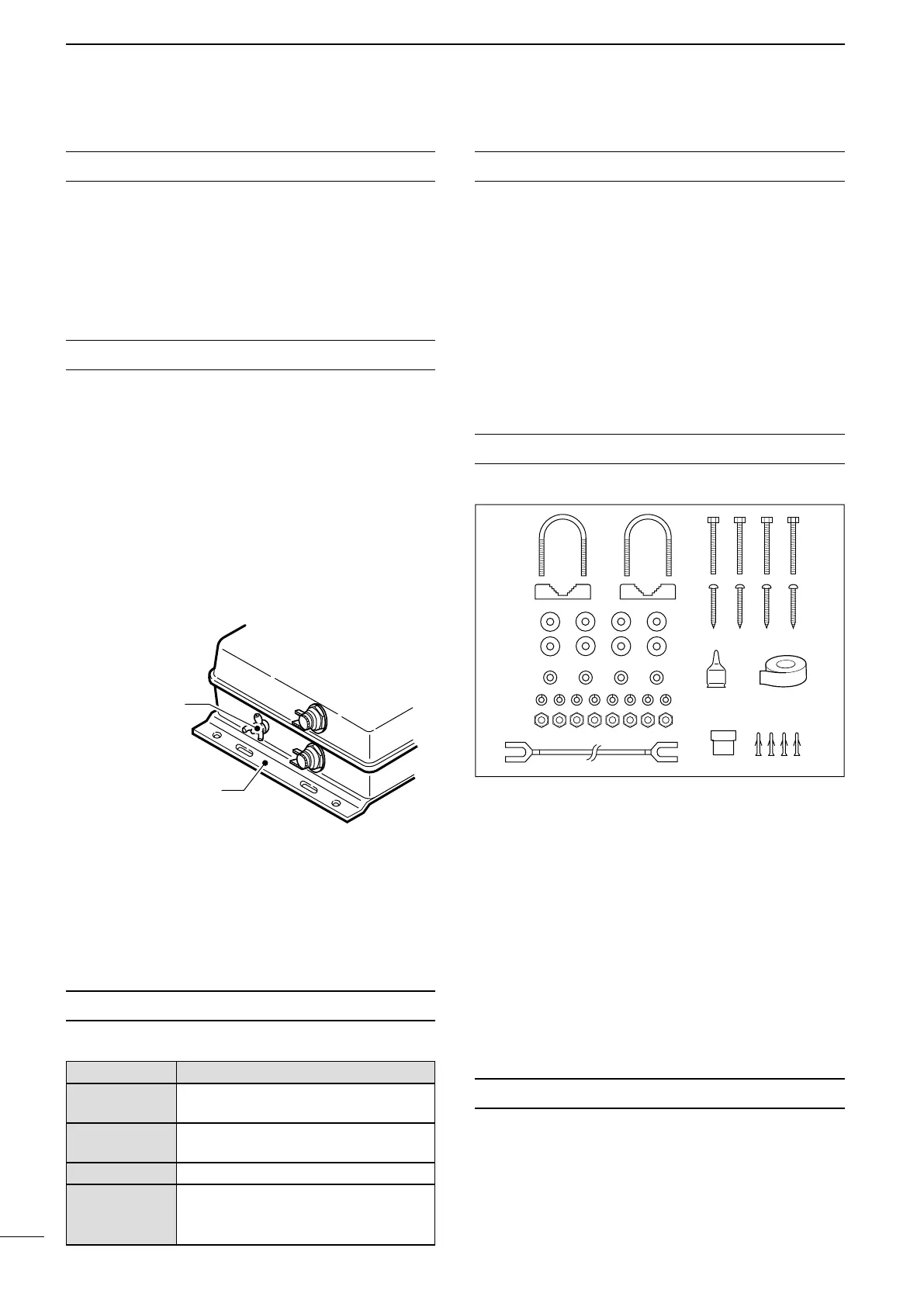
SUPPLIED ACCESSORIES
The following parts are supplied with the AT-130/E.
Qty.
q U-bolts ������������������ 2
w U-bolt plates ��������������� 2
e Flat washers (M6 large) ���������� 8
r Flat washers (M6 small) ���������� 4
t Spring washers (M6) ������������ 8
y Nuts (M6) ����������������� 8
u Hex head bolts (M6×50) ���������� 4
i Self-tapping screws (A0 6×30) �������� 4
o Weatherproof cap ������������� 1
!0 Rubber vulcanizing tape ���������� 1
!1 4-pin connector �������������� 1
!2 Connector pins �������������� 4
!3 Ground cable (OPC-412) ���������� 1
MISCELLANEOUS ITEMS
The following parts are required for installation, but are
not supplied with the AT-130 or AT-130E.
q AWG 14×4-conductor shielded cable
* Icom offers an optional OPC-420 c o n t r o l c a b l e .
Length: 10 m; 32.8 feet
w 50 Ω coaxial cable
e Two PL-259 connectors
 Loading...