4
2
INSTALLATIONS
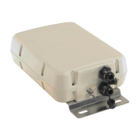
n Control cable
Between the AT-130/E and HF marine transceiver,
connect four control signal lines as shown at right. To
prevent RF feedback, use a four conductor shielded
cable. Connect the shield line to the [GND] terminal
on the transceiver.
Icom offers the 10 m (32.8 feet) long control cable,
OPC-420 c o n t r o l c a b l e .
Refer to page 9 “Terminal information” and “Trans-
ceiver switch” for details.
[GND]
To the AT-130/E
For an optional OPC-420
CONTROL
CABLE
,
you need to not assemble the supplied
four pin connector.
To the Icom HF marine
transceiver
Control cable
AT-130E : [E]
AT-130E : [ANTC]
[13.6]
[STAR]
[KEY]
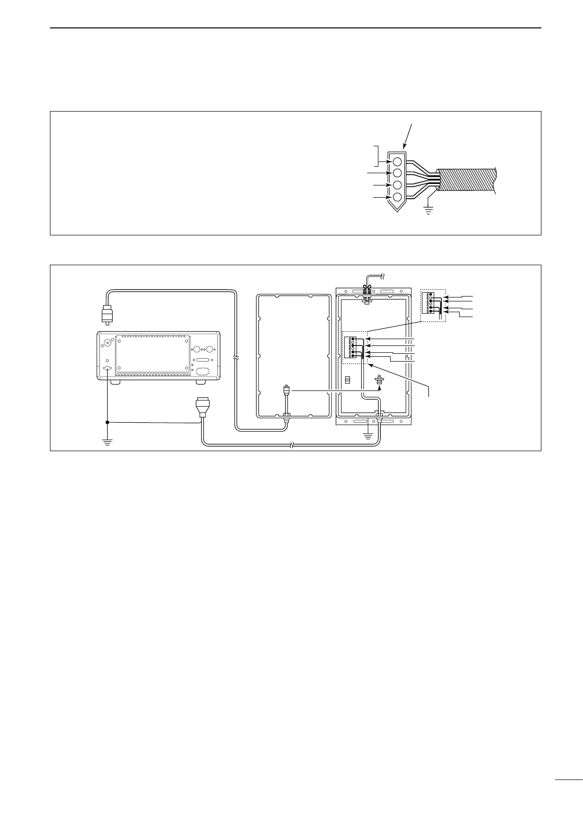
n Cable connections
Coaxial cable
Icom HF transceiver
AT-130
AT-130E
PL-259
connector
To antenna
element
PL-259
connector
[E]
[13.6]
[STAR]
[KEY]
[ANTC]
[13.6]
[STAR]
[KEY]
[ANT]
[GND]
[TUNER]
4-pin connector
Ship’s ground
Ship’s ground
Control cable
Before connecting to terminals,
tin each end of the cable’s wires.
Connect to the [ANTC]
terminal instead of the
[E] terminal.
Refer to page 7 for
details.
 Loading...