2
3
INSTALLATIONS
n Installation outline
q Remove the top cover.
w Install a control cable and coaxial cable.
• Refer to “Cable installation” as described below.
e Connect and solder the PL-259 connector to the
coaxial cable.
• Refer to “PL-259 connector” as described below.
r Connect the control cables to the AT-130/E.
• Refer to page 4, “Cable connections.”
t Mount the AT-130/E in the desired location.
• Refer to page 6, “Mounting.”
y Connect an antenna, ship’s ground or counter-
poise.
• Refer to page 1, “Antenna for ship” and page 2,
“Ground and counterpoise.”
u Connect the control cable and the coaxial cable to
the transceiver.
• Refer to page 4, “Control cable.”
i Perform preset tuning setting. For the AT-130E,
also perform emergency tuning setting.
• Refer to page 7, “Preset tuning” and page 8, “Emer-
gency tuning.”
o Select the mode switch (S1) to NORMAL mode
(center position). Replace the top cover.
n PL-259 connector
q
Slide the coupling ring down.
Strip the cable jacket and tin the shield.
Coupling
30 mm
10 mm (tin here)
w
Strip the cable as shown below.
Tin the center conductor.
e Slide the connector body on and solder it.
r Screw the coupling ring onto the connector body.
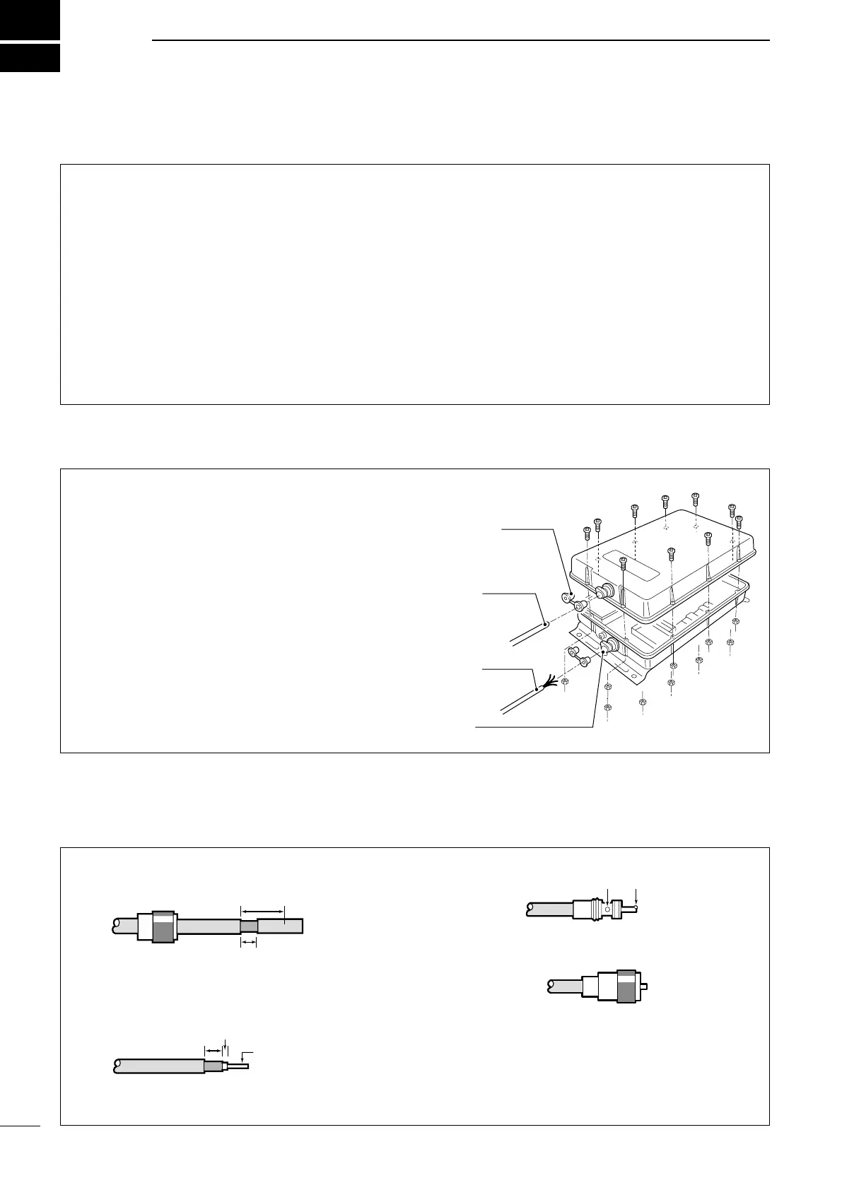
n Cable installation
q Remove the 10 screws from the top cover. Re-
move the top cover.
w Loosen the screws on both cable clamps.
e Set or remove the strain relief inserts correspond-
ing to the diameters of the cables.
r Install the coaxial cable through the top cover
cable clamp. Install the control cable through the
bottom cover cable clamp.
t After connecting the coaxial cable and control ca-
bles, perform the preset tuning setting.
• For the AT-130E, also perform emergency tuning set-
ting.
y After internal adjustments, tighten the cable clamp
screws.
Strain relief
Coaxial
cable
Control
cable
Cable
clamp
30 mm (1
3
⁄16 inches) 10 mm (
13
⁄32 inches) 1–2 mm (
1
⁄32–
3
⁄32 inches)
 Loading...