B - 3 - 1
SECTION 3 CIRCUIT DESCRIPTION
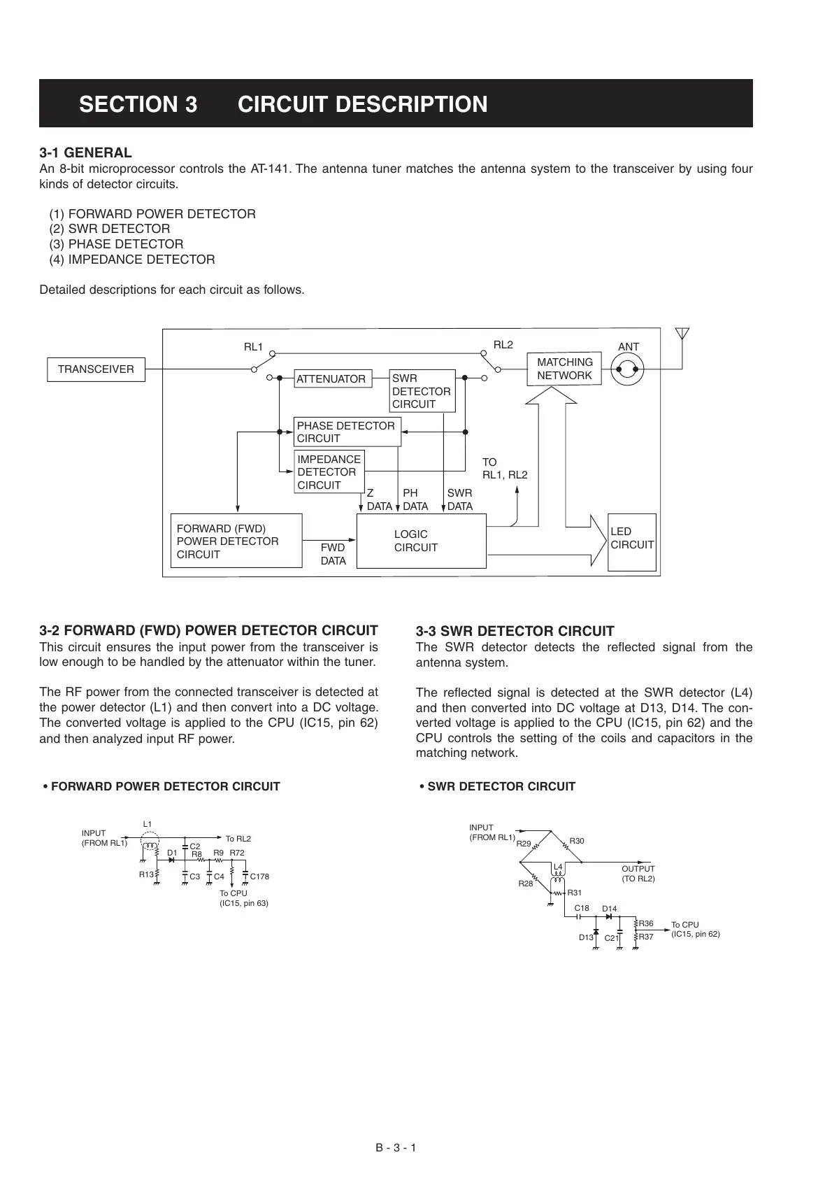
3-1 GENERAL
An 8-bit microprocessor controls the AT-141. The antenna tuner matches the antenna system to the transceiver by using four
kinds of detector circuits.
(1) FORWARD POWER DETECTOR
(2) SWR DETECTOR
(3) PHASE DETECTOR
(4) IMPEDANCE DETECTOR
Detailed descriptions for each circuit as follows.
FORWARD (FWD)
POWER DETECTOR
CIRCUIT
TRANSCEIVER
FWD
DATA
TO
RL1, RL2
Z
DATA
PH
DATA
SWR
DATA
LOGIC
CIRCUIT
LED
CIRCUIT
IMPEDANCE
DETECTOR
CIRCUIT
PHASE DETECTOR
CIRCUIT
SWR
DETECTOR
CIRCUIT
MATCHING
NETWORK
ATTENUATOR
RL1
RL2
ANT
3-2 FORWARD (FWD) POWER DETECTOR CIRCUIT
This circuit ensures the input power from the transceiver is
low enough to be handled by the attenuator within the tuner.
The RF power from the connected transceiver is detected at
the power detector (L1) and then convert into a DC voltage.
The converted voltage is applied to the CPU (IC15, pin 62)
and then analyzed input RF power.
C3
C2
D1
L1
R13
R8
R72R9
To CPU
(IC15, pin 63)
To RL 2
INPUT
(FROM RL1)
C4 C178
• FORWARD POWER DETECTOR CIRCUIT
L4
R30
R29
R28
(FROM RL1)
R31
C18
D14
C21
R37
D13
INPUT
To CPU
(IC15, pin 62)
R36
OUTPUT
(TO RL2)
• SWR DETECTOR CIRCUIT
3-3 SWR DETECTOR CIRCUIT
The SWR detector detects the reflected signal from the
antenna system.
The reflected signal is detected at the SWR detector (L4)
and then converted into DC voltage at D13, D14. The con-
verted voltage is applied to the CPU (IC15, pin 62) and the
CPU controls the setting of the coils and capacitors in the
matching network.
 Loading...