B - 4 - 2
4-2 TUNER ADJUSTMENT
ADJUSTMENT ADJUSTMENT CONDITION
MEASUREMENT
VALUE
ADJUSTMENT
UNIT LOCATION UNIT ADJUST
PREPARA-
TION
1 • Disconnect short pin (P6) from J6
• Connect the disconnected short pin (P6) to J13.
• Connect a wire between CP15 and ground.
• TRANSCEIVER
Display frequency : 1.6000 MHz
Output power : 10 W (Carrier only)
FORWARD
DETECTOR
CIRCUIT
2 • Transmit the transceiver.
TUNER
Connect a voltme-
ter to CP81.
1.4 – 2.4 V TUNER Verify
SWR DE-
TECTOR
CIRCUIT
3 • Transmit the transceiver. Connect a voltme-
ter to CP84.
0 – 0.1 V Verify
PHASE
DETECTOR
CIRCUIT
4 • Transmit the transceiver. Connect an oscil-
loscope to CP81.
5 V (Set R194 at
the point where the
voltage just before
drops to 0 V.)
R194
IMPEDANCE
DETECTOR
CIRCUIT
5 • Transmit the transceiver. Connect an oscil-
loscope to CP83.
5 V (Set C7 at the
point where the
voltage just before
drops to 0 V.)
C7
NOTE:
• After the adjustment, remove the jumper wire between CP15 and ground.
• After the adjustment, disconnect short pin (P6) from J13.
• After the adjustment, connect the disconnected short pin (P6) to J6.
• While the adjustment the transmitting time as short as possible.
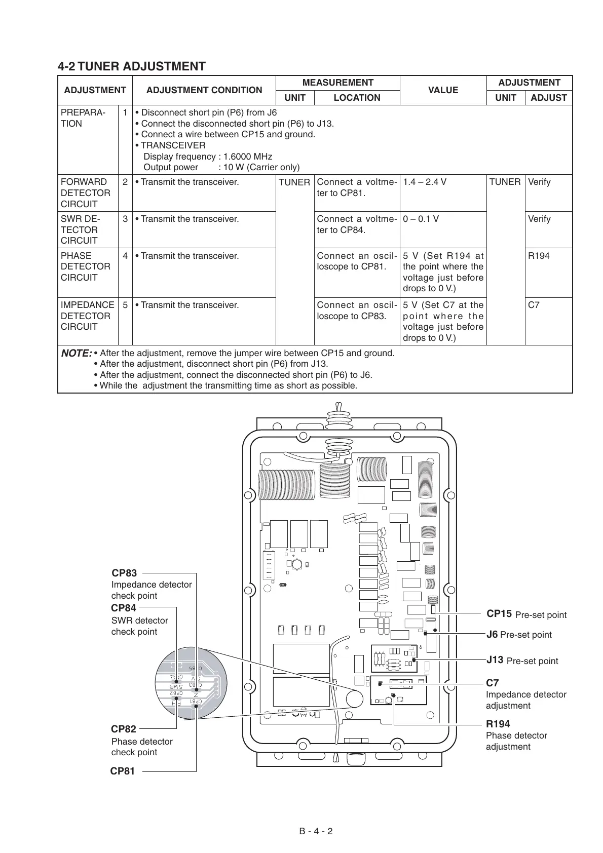
C7
J13
CP84
R194
Impedance detector
adjustment
Pre-set point
J6
Pre-set point
CP15
Pre-set point
SWR detector
check point
CP82
Phase detector
check point
CP83
Impedance detector
check point
Phase detector
adjustment
 Loading...